
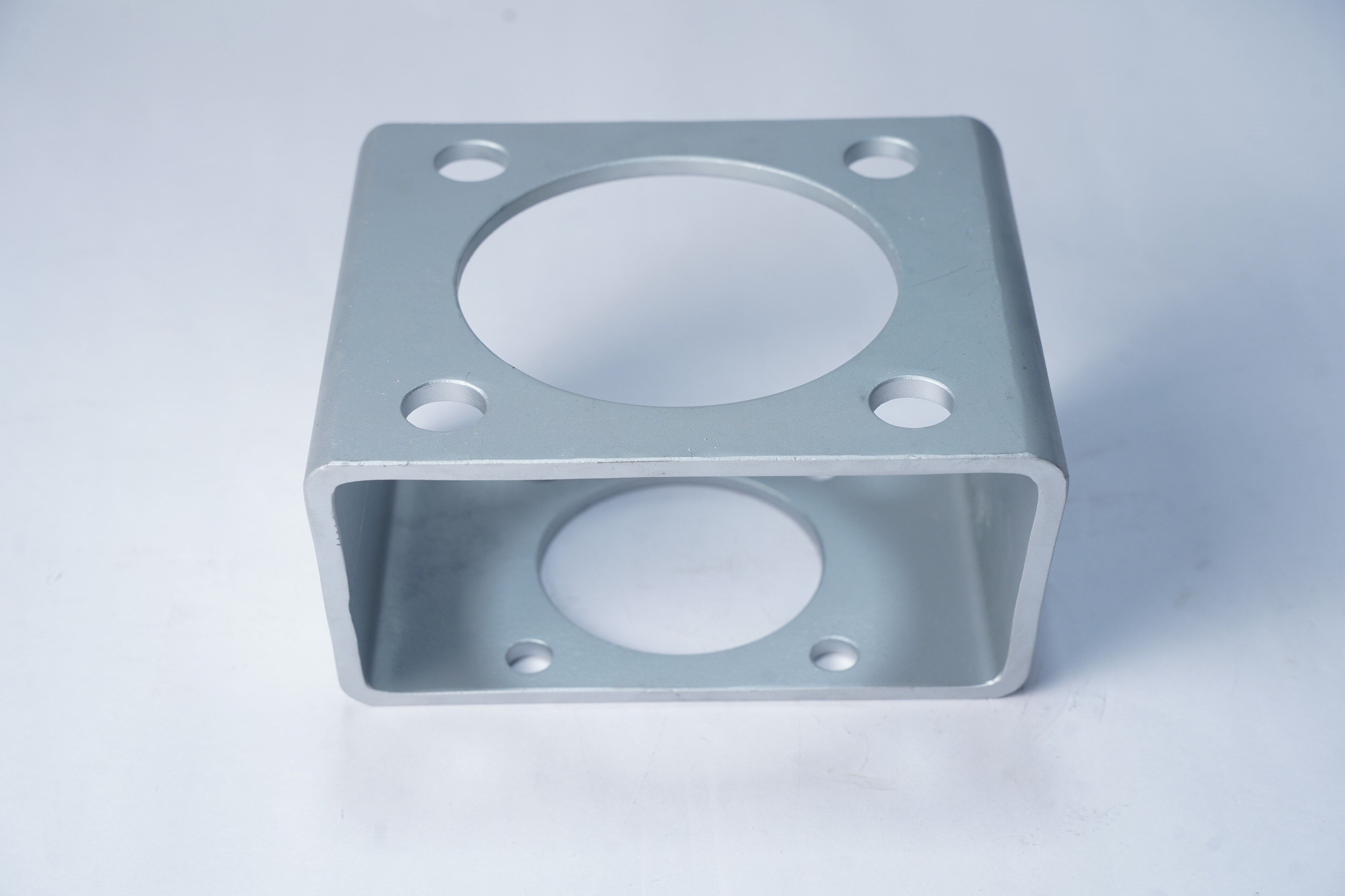
A bracket adaptor can pass visual inspection and still misalign an actuator, loosen fasteners, or fail under breakaway torque. You will learn how to identify the correct component, isolate and inspect it, measure its interfaces, decide whether to repair or replace it, and issue a replacement specification that prevents another fit-up failure.
Key takeaways
- Match the adaptor part number, drawing revision, valve and actuator before removal.
- Measure pilot diameter, bolt pattern, thickness, flatness and shaft clearance.
- Reject cracked, distorted or loose adaptors; repair only against an approved procedure.
- Specify material, tolerances, finish, testing and traceability when sourcing a replacement.
Identify the adaptor and remove it without creating a second fault
Confirm the adaptor against the controlled assembly drawing before touching a fastener. Match the valve make and model, adaptor part number and revision, actuator model, mounting-flange pattern, pilot diameter, stem or shaft profile, and orientation marks.
ISO 5211 defines common part-turn interfaces, but it does not prove that this adaptor fits your specific valve and actuator.
A valve-shell pressure test under API 598 or ISO 5208 does not validate adaptor alignment, torque capacity, or actuator geometry. Isolate the valve and actuator, shut off energy sources, depressurise the line, and apply lockout/tagout. Treat the assembly as live until you verify zero pressure and a safe actuator state.
Use this removal sequence:
- Photograph the assembly and mark the adaptor, valve, actuator, and coupling orientation.
- Support the actuator independently; never let its weight hang from the adaptor or valve stem.
- Follow the manufacturer’s sequence to disconnect power, controls, and the actuator coupling.
- Loosen fasteners evenly, then remove them without driving a wedge between mating faces.
- Lift the adaptor straight off. Do not hammer the stem, twist against the valve seat, or force a seized joint.
- Bag the fasteners and record their grade, length, washers, and locations.
Keep removed parts clean and labelled. This basic control prevents a second fault—misorientation, bent coupling parts, damaged threads, or contaminated faces—during industrial valve adaptor maintenance. Cycle the valve only after reassembly and alignment checks.
Clean, inspect and measure every load-bearing feature
A bracket adaptor inspection starts with cleaning, because oil, paint and oxide can hide a crack or make a worn bore appear sound. Use a solvent that will not attack the material, a non-metallic brush, and bright angled lighting; dry the adaptor before measuring it.
1. Record material or heat-lot identification, then inspect the bore, pilot, shoulders, flange, keyway, threads and mounting holes for fretting, galling, dents, burrs, stripped threads and elongated holes.
2. Check for distortion against a flat reference surface. Measure flange parallelism, flatness, overall height and wall thickness from the drawing’s stated datums, not from an arbitrary outside surface.
3. Separate staining from structural corrosion. Light discoloration that leaves sound metal after cleaning is not the same as pitting, reduced wall thickness or a sharp-edged cavity. Reject any area beyond the drawing’s minimum thickness.
4. Examine suspect lines with magnification and a suitable dye-penetrant or magnetic-particle method for the material. A line that accepts penetrant, crosses a fillet or grows from a hole is a crack, not a harmless machining mark.
5. Measure critical diameters, pilot and bore fits, shaft or keyway dimensions, mounting-hole true position and thread condition in a repeatable, low-distortion fixture after thermal stabilisation.
6. Check coaxiality of the valve stem, adaptor bore and actuator output before final tightening and again after cycling. Misalignment can hide behind a flexible coupling and later cause high actuator current, uneven seating, fretting, shaft wear, bracket distortion or loose fasteners.
Keep the adaptor only when every result meets the drawing and fit requirements; record each measurement and photograph any defect.
Verify fit, material and operating compatibility before approval
A 1 mm mismatch at the pilot, shaft bore or mounting face can create eccentric actuator loading, even when the adaptor appears visually sound. Check the valve and actuator drawings together; ISO 5211 identifies part-turn mounting-flange and drive interfaces, but it does not prove that two adaptor designs interchange.
Check these items against the approved assembly drawing:
- Mounting-flange diameter, bolt-circle diameter, hole quantity, hole diameter, thread type, pilot diameter and pilot depth.
- Adaptor thickness, face flatness, shaft-bore diameter, key or square-drive size, engagement length and concentricity between the valve and actuator interfaces.
- Material grade, heat treatment, surface coating, corrosion compatibility and galvanic contact with the valve, actuator and fasteners.
- Breakaway torque, maximum differential-pressure torque, packing friction, actuator shutoff torque, temperature effects and corrosion-related increases in resistance.
- Fastener size, grade, tightening method and available thread engagement; the adaptor, bolts, shaft and drive feature must carry the combined torque and reaction load.
| Check | Evidence before approval |
|---|---|
| Interface fit | Controlled drawing and dimensional report referenced to the valve and actuator data |
| Material suitability | Material certificate, heat-treatment record and coating or special-process record |
| Load capacity | Torque calculation covering the worst operating condition, not only the actuator nameplate rating |
| Assembly function | Manual or powered full-stroke test with correct stops, travel and alignment |
A valve pressure test to API 598 or ISO 5208 addresses leakage and pressure performance, not adaptor alignment or coupling. Require calibration status for measuring equipment and documented inspection results; supplier location alone proves nothing.
Choose between reuse, repair and replacement using defined acceptance criteria
A damaged adaptor is repairable only when the defect is local, removable, and the finished part will meet the approved drawing without weakening the load path. A valve bracket repair that merely hides a crack, restores a distorted pilot, or fills an elongated hole is not acceptable.
| Option | Acceptance basis | Decision |
|---|---|---|
| Reuse | No cracks; corrosion is superficial; threads, shoulders, holes, flatness, concentricity and wall thickness remain within drawing tolerances | Approve after fit and function checks |
| Repair | A qualified process removes the defect, preserves material strength, and post-repair inspection confirms every specified dimension and interface | Release only with repair and inspection records |
| Replace | Crack, bent or distorted geometry, loose pilot, fretted or distorted shaft interface, moved mounting holes, unrecoverable thread damage, or unverifiable material and heat treatment | Reject the adaptor and install a controlled replacement |
Reject any part whose repair would reduce wall thickness below the drawing minimum, alter the ISO 5211 interface, or leave uncertain load capacity. Do not treat surface paint or pressure-test results as proof of acceptability.
Plan industrial valve adaptor maintenance by operating cycles, torque trend, environment and failure consequences. During scheduled maintenance:
- Check fastener torque using the specified tightening method.
- Inspect for fretting, corrosion and coupling engagement.
- Cycle the valve and record torque, travel and seating behaviour.
API 598 or ISO 5208 pressure tests address valve leakage and pressure performance; they do not confirm adaptor alignment or actuator coupling. Functional testing must prove smooth, complete travel without binding, abnormal torque or mounting movement.
Write a controlled replacement specification and evaluate a Pune supplier
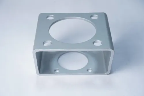
Send a controlled drawing and inspection plan to a bracket adaptor supplier in Pune. Identify the industrial valve bracket adaptor for replacement by valve make and model, stem or shaft geometry, actuator torque, rotation angle, mounting-flange pattern, pilot diameter, bolt grade and length, envelope, and fail-safe direction.
1. State the material grade, heat-treatment condition, surface finish, thread standard, keyway details, geometric tolerances, datum scheme, and drawing revision. Do not let the supplier select dimensions from nominal valve size alone.
2. Require a quotation that names machining capability, proposed special processes, subcontractors, production lead time, and lot traceability. Location does not prove interchangeability; the approved drawing and interface data do.
3. Before acceptance, obtain the material certificate with heat or lot number, machining revision, special-process records, and calibration certificates for measuring equipment used on the lot.
4. Require a dimensional report tied to the drawing datums. It must record critical diameters, pilot and bore fits, hole true position, flange parallelism, overall height, shaft or keyway dimensions, threads, and surface condition.
Efficient Precision & System Pvt.Ltd. should be evaluated against those records and its ability to reproduce the controlled revision, not against a catalogue description.
Inspect the replacement before installation, then verify coaxiality of the valve stem, adaptor bore, and actuator output before final tightening and after cycling. Request a documented functional stroke test, including actuator current, seating, direction, and fastener condition.
API 598 or ISO 5208 pressure-test records address valve leakage; they do not replace dimensional, coupling, alignment, or assembly testing.
Related product
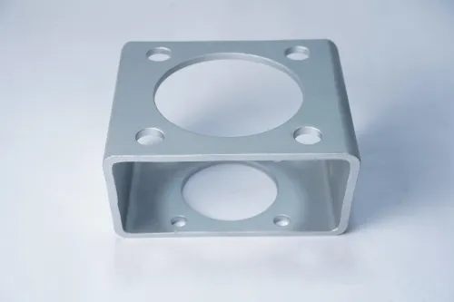
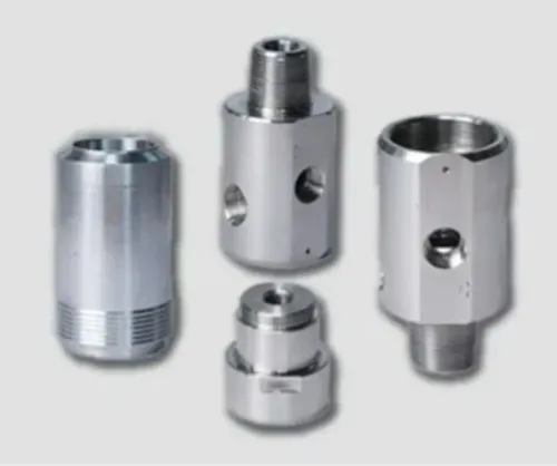
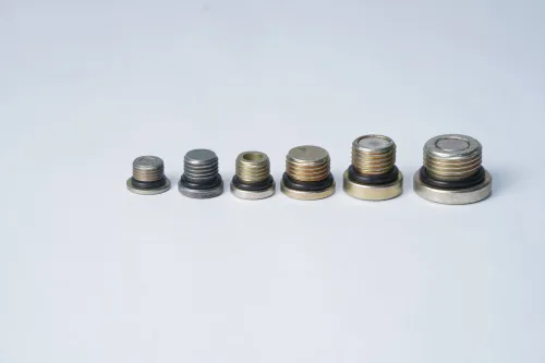
 | Industrial Valve Efficient Precision and System Pvt. Ltd. is a leading supplier, exporter and manufacturer of Valve Brackets based in India. View product → |
Frequently asked questions
How do you identify an industrial valve bracket adaptor before removal?
Match the controlled assembly drawing with the valve make and model, adaptor part number and revision, actuator model, mounting-flange pattern, pilot diameter, stem or shaft profile, and orientation marks. Record the installed position before loosening fasteners.
What features should you measure during bracket adaptor inspection?
Measure the mounting-hole pattern, pilot diameter, adaptor thickness, bore or shaft clearance, flatness, parallelism, thread condition and any load-bearing shoulders. Check for cracks, fretting, corrosion, distortion and elongated holes.
When should a valve bracket adaptor be repaired, reused or replaced?
Reuse an adaptor only when measurements remain within the controlled drawing limits and no crack, distortion or thread damage exists. Repair requires an approved method and post-repair inspection. Replace it when a load-bearing feature is cracked, permanently distorted, excessively worn or outside tolerance.
What should a replacement valve bracket adaptor specification include?
State the valve and actuator models, drawing revision, material grade, heat-treatment condition, dimensions, tolerances, surface finish, hole and thread details, orientation, inspection records, marking and material traceability.
How should you evaluate a bracket adaptor supplier in Pune?
Check the supplier’s machining capability, inspection equipment, material traceability, drawing-control process, sample inspection report, nonconformance handling and ability to produce the required tolerances. Request evidence for the specific part rather than relying on general capability claims.