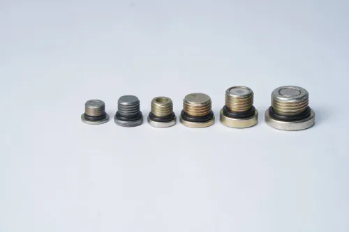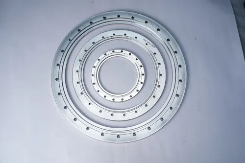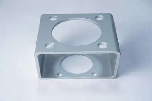

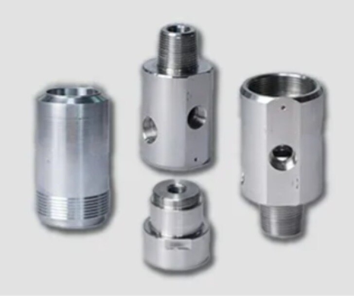
A vehicle part can meet its size dimensions and still leak, vibrate, seize or fail to assemble when its datums, runout, hole position, threads or surface condition are wrong. You will be able to match each automotive geometry to a machining process, identify failure risks and judge whether a supplier has evidence of repeatable production.
Key takeaways
- Match the machining process to geometry, tolerance, access, and production volume.
- Inspect runout, flatness, perpendicularity, burrs, taper, and surface finish—not diameter alone.
- Request inspection reports, material certificates, traceability, and approved samples before repeat production.
- Control tool wear, workholding, coolant, and first-off inspection during production runs.
How precision controls fit, sealing, rotation and safety
Automotive parts need CNC and VMC precision components because fit, sealing, rotation and load transfer depend on geometry that ordinary size checks cannot prove. A shaft can meet its diameter tolerance yet wobble in a bearing; a valve body can meet its bore size yet leak because its sealing face is not flat or square.
These failures create vibration, wear, noise and safety risks.
| Specification | Function controlled | Failure when missed |
|---|---|---|
| Total runout between diameters | Bearing and shaft rotation | Eccentric rotation, uneven wear |
| Perpendicularity of a shoulder | Bearing or spacer seating | Axial misalignment and preload |
| True position of a cross-hole | Pin, injector or fastener assembly | Difficult assembly or weakened retention |
| Flatness of a sealing face | Gasket or metal-to-metal sealing | Fluid or gas leakage |
Define these controls with GD&T and a clear datum scheme. Surface roughness matters too: a rough seal leaks, while a rough bearing journal accelerates wear. Thread class, chamfer size and edge condition affect assembly, and a burr can block an oil passage or cut a seal.
Specify dimensions before and after heat treatment or plating when those operations change size. Ask for measurement-system evidence, not only a first-off dimension report. A capable CNC or VMC process must hold the feature relationship repeatedly, control thermal drift and deliver clean, burr-free parts that remain traceable to their material lot.
Choose the process for the part geometry, not the machine name
A shaft with several diameters is not automatically a Swiss-job. Choose the process from the geometry, material, volume and required evidence. CNC VMC parts for automotive use need a route that holds functional relationships at production volume, not simply the machine with the most axes.
| Process | Geometry or material | Choose it when |
|---|---|---|
| CNC turning | Rotational shafts, pins, threads and seats | The part is mainly round and needs accurate diameters, grooves or threads. |
| Swiss-type sliding-head machining | Small, slender shafts, sleeves, valve spools and injector-related parts | A guide bushing must support material close to the cutting tool to limit deflection. |
| VMC milling | Brackets, housings, pockets, slots, cross-holes and bolt patterns | Several faces, datums or angled features must remain accurately related. |
| Conventional turning | Larger, simple rotational parts | Tolerances, surface finish and volume do not justify CNC automation. |
| Casting | Complex near-net-shape metal housings | Large quantities reduce tooling cost and machining is limited to critical surfaces. |
| Forging | High-load steel or aluminium parts such as connecting or steering components | Grain flow and strength matter more than intricate finished geometry. |
| Stamping | Thin sheet brackets, clips and shields | The part is flat or formed from sheet at high volume. |
| Injection moulding | Polymer clips, covers, ducts and retainers | Complex plastic geometry and low unit cost outweigh mould-tool expense. |
One multi-axis operation can reduce setup and datum-transfer errors, but it raises programming and maintenance risk. A Swiss part with milling features may need live tooling, a second operation or VMC transfer; compare cycle time, fixture repeatability, inspection capability and total cost before choosing.
Prevent burrs, taper, chatter and material-related failures
A shaft can pass its diameter check and still fail in assembly if taper, runout or chatter marks prevent smooth rotation. Burrs at a cross-drilled oil passage can restrict flow, break loose in service or stop a valve spool from moving; deburring can also damage a sealing edge or enlarge a small chamfer.
Material condition changes the cutting result. Hardened steel accelerates tool wear, aluminium can build up on a tool, and brass needs chip control that prevents scratches and trapped swarf.
Choose the insert grade, edge geometry, cutting speed and feed for the alloy and hardness, then replace worn tools before taper, poor surface finish or damaged threads enter the lot.
- Clamping: support slender parts close to the cut; a Swiss-type guide bushing reduces deflection, while excessive VMC clamping force can distort thin walls.
- Coolant: control concentration and cleanliness, break chips, flush drilled passages, wash and dry parts, then package them without trapped residue.
- Heat treatment and coating: allow for size change or distortion, inspect at the defined stage, and reserve coating allowance where plating adds uneven thickness.
- Finishing: define the deburring method and acceptance limit; inspect sealing faces, hole position, perpendicularity and total runout against named datums.
Record the raw-material heat or batch, machining route, treatment supplier, inspection results and rework disposition. That traceability separates a material-related failure from a machining failure when automotive precision component problems reach assembly.
Specify and inspect the evidence that proves a part is acceptable
Before quoting, provide the controlled drawing, revision level, material grade and heat-treatment condition, annual volume, lot size, critical characteristics and required delivery condition. Define every datum, tolerance, surface-finish value, geometric tolerance, thread standard and class, coating or plating thickness, deburring limit, cleanliness requirement and inspection temperature.
State whether dimensions apply before or after heat treatment and coating.
| Feature | Specify on drawing | Evidence to request |
|---|---|---|
| Thread | Standard, class, lead-in chamfer, cleanliness and GO/NO-GO gauging | Thread-gauge results and visual records of first-thread condition |
| Hole or datum pattern | Size, position tolerance, datum scheme and depth | CMM or calibrated gauge report with actual values |
| Sealing or bearing surface | Flatness, roundness, runout, finish and edge condition | Surface-finish, form and visual inspection results |
| Heat-treated or plated feature | Final hardness, thickness and post-process dimensions | Material, hardness, coating and final dimensional reports |
For automotive machined parts, request a record set that proves function rather than a certificate showing only overall dimensions:
- Signed dimensional inspection report identifying drawing revision, part number, serial or lot number, instrument ID and actual readings.
- Calibration certificates and measurement-system analysis, including gauge repeatability and reproducibility for critical measurements.
- Material certificate, heat-treatment report and performance-test results where strength, hardness, pressure, torque or fatigue affects use.
- Capability studies for critical dimensions, with reaction plans for out-of-control results.
- PPAP records: process flow, PFMEA, control plan, initial process studies and Part Submission Warrant.
Move from prototype to controlled repeat production
Prototype approval proves that one part met the drawing; repeat production proves that the next 10,000 parts will behave the same way. Evaluate a CNC component supplier in Pune on documented control of the process, not on machine count or first-off inspection alone.
1. Request the production evidence: process flow, PFMEA, control plan, measurement-system analysis, dimensional results, material or performance tests, initial process studies and the Part Submission Warrant. Check that each document names the same revision, characteristic numbers and acceptance limits.
2. Match capability data to your risk features. For a shaft, review total runout between diameters; for a housing, review true position of holes and perpendicularity of shoulders. Treat Cpk as useful only with the characteristic, sample size, time period, control chart, measurement suitability and specification limits stated.
3. Verify traceability from incoming material heat or batch number through machine, operator, inspection record, subcontracted treatment and shipment. Ask what happens after an out-of-control signal: stop, segregate, investigate, correct and re-inspect—not simply continue machining.
4. Compare envelope and axis capacity alongside fixture repeatability, tool and spindle condition, calibration dates, inspection equipment, takt-time capacity and subcontractor controls. Efficient Precision & System Pvt.Ltd should be assessed by the same evidence as any supplier.
5. Inspect production samples for chips, coolant residue, burrs and damaged packaging. The control plan must cover chip breaking, flushing, washing, drying and packaging, because a clean, traceable part is what reaches assembly—not merely an in-tolerance part.
Related product
 | CNC & VMC Precision Component Efficient Precision & System Pvt. Ltd. is an established and reputable company specializing in manufacturing and supplying CNC precision components... View product → |
Frequently asked questions
Why do automotive parts need CNC and VMC precision components?
Automotive components rely on controlled geometry for bearing fit, sealing, rotation, alignment, load transfer, and safety. A diameter check alone cannot prove those functions.
How do you choose between CNC and VMC machining for an automotive part?
Choose the process from the part geometry. Sliding-head or CNC turning suits slender shafts and rotational features, while VMC machining suits prismatic parts, drilled patterns, pockets, and multiple faces.
Which automotive precision component problems should inspection catch?
Inspection should identify burrs, taper, chatter marks, excessive runout, poor flatness, incorrect perpendicularity, damaged threads, and material-related defects.
What evidence proves an automotive machined part is acceptable?
Request a controlled drawing revision, first-off inspection report, calibrated measurement records, material certificate, surface-finish results where specified, and traceability to the production batch.