
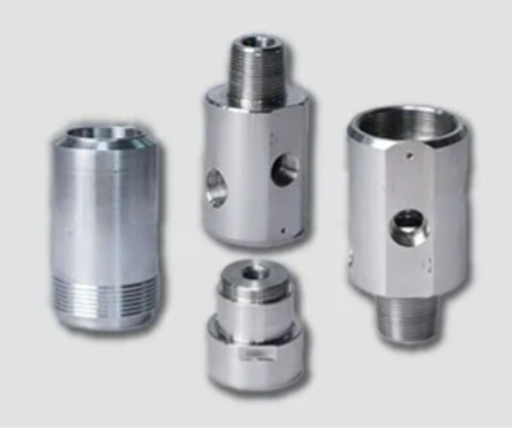
A finished component is only as reliable as the decisions made before the first tool touches the material. Follow the drawing through datum planning, machine selection, setup, first-off validation, production controls and measurement so you can judge whether a process is capable of producing an acceptable part.
Key takeaways
- Set datums from functional surfaces before creating CNC toolpaths.
- Sequence roughing, finishing and inspection to protect accuracy.
- Validate the first-off part before releasing production.
- Record tool wear, burr control and traceability details during machining.
Turn the Drawing into a Feature and Datum Plan
Before a CNC program is written, convert the drawing or 3D CAD model into a feature-and-datum plan; that is the foundation of how CNC VMC precision components are made. Do not create toolpaths from model geometry alone.
- Confirm the drawing number, revision, units, scale, and material grade and condition. Record the required stock size, machining allowance, heat treatment, coating, and material traceability.
- Identify the functional datums and reproduce their order, such as datum A, B, and C. Separate the inspection datum reference frame from the machine’s convenient programming zero.
- List every critical feature: faces, bores, holes, slots, threads, radii, chamfers, thin walls, and sealing surfaces. Mark each size tolerance, position, flatness, perpendicularity, concentricity, runout, and surface-finish requirement.
- Confirm thread designation, pitch, depth, class, and whether acceptance requires a plug or ring gauge. Define edge-break, burr, and sharp-edge limits instead of leaving them to operator judgement.
- Decide how each feature will be inspected, including instrument, resolution, datum simulation, fixturing, sampling frequency, and acceptance criterion.
A feature-control frame must be tied to the same datum structure during inspection. Measuring a hole from an arbitrary edge can produce an acceptable number while the hole fails its specified position. Record the selected work coordinate, feature sequence, allowances, and critical characteristics before choosing tools.
This plan prevents a model-origin mismatch from becoming a rejected part after machining.
Choose the Machine, Workholding and Operation Sequence
A VMC is a CNC milling machine, so the decision starts with the part’s geometry rather than the machine label. Use milling for faces, pockets, slots, cross-holes and angled features; choose sliding-head machining when a small diameter and long length-to-diameter ratio make unsupported turning likely to deflect.
The cnc vmc component manufacturing process must also account for tool access, stock removal and the number of setups.
| Option | Best fit | Main control |
|---|---|---|
| CNC milling | Prismatic features and secondary operations | Confirm cutter access and rigid support |
| VMC | Faces, pockets, flats, cross-holes and multi-side work | Use a suitable fixture or multiple-axis indexing |
| Sliding-head | Small, slender turned parts and repeated diameters | Set guide-bushing clearance, bar extension and cutoff allowance |
Locate the part from functional drawing datums, not from whichever edge is easiest to grip. Use a 3-2-1 fixture, soft jaws, a collet, locating pins or a guide bushing as the feature requires; then probe or indicate the datum surfaces and record the work offset.
A part transferred from a Swiss machine to a VMC needs special care: clamping a thin wall or finished diameter can distort it, so support an unfinished, rigid area and verify dimensions unclamped.
Plan roughing, drilling, boring, milling and finishing in an order that protects datums and leaves controlled stock for final cuts.
Efficient Precision & System Pvt.Ltd can apply the same logic to valve parts: control clamping pressure, coolant temperature, warm-up and tool life so thermal drift does not turn an accurate first piece into a later failure.
Related product
 | CNC & VMC Precision Component Efficient Precision & System Pvt. Ltd. is an established and reputable company specializing in manufacturing and supplying CNC precision components... View product → |
Machine the Blank and Validate the First-Off Part
At material receipt, verify the mill certificate, material grade, heat or lot number, bar or plate size, and material condition against the drawing and job traveller. Record the identification before cutting the blank, then remove scale, saw damage, and excess stock that could prevent secure location in the VMC.
The precision component machining process follows a controlled sequence:
- Cut the blank with enough allowance for clamping, roughing, finishing, and cutoff loss.
- Warm the spindle and machine, stabilise coolant concentration and temperature, and load verified tools with known offsets.
- Face and rough-mill the stock, removing most material while limiting cutting force, heat, and tool wear. Leave a consistent finishing allowance; too little stock lets deflection and insert wear show up as dimensional drift.
- Finish faces, pockets, flats, profiles, and other critical surfaces with a stable tool and controlled engagement.
- Drill holes, then bore or ream them when the drawing requires tighter size, position, or surface-finish control.
- Tap threads with the specified pitch and depth, then remove burrs without rounding functional edges.
- Wash and dry the component to remove chips, abrasive residue, and coolant, then mark the approved identification without damaging a datum or sealing surface.
The operator treats the first-off part as unapproved until inspection reproduces the drawing datums and checks critical dimensions, geometric tolerances, threads, surface finish, and marking. Record actual results against acceptance limits; release production only after an authorised reviewer signs the first-off approval, or correct the offsets and repeat the inspection.
Control Tools, Heat, Burrs and Traceability During Production
An approved setup can drift during production. The cnc vmc component manufacturing process controls heat, tool wear and clamping force instead of assuming the first-off approval remains valid.
- Run a spindle warm-up cycle, then hold coolant temperature, concentration and flow within defined limits before taking critical measurements.
- Rough with controlled engagement and leave a consistent finishing allowance; finishing with too little stock makes deflection or insert wear look like dimensional drift.
- Set tool-life limits by parts, cutting time or wear readings, and verify critical dimensions at scheduled intervals as the machine reaches thermal equilibrium.
- Support thin walls and transferred turned parts without clamping finished diameters; release distortion can disappear during measurement and return in service.
- Specify edge-break or burr limits, use a controlled deburring operation, and inspect holes, slots and intersecting edges under magnification. A burr can change fit, flow or the measured dimension.
Maintain a traceability record for every production run:
- Material heat or lot, including hardness or condition when it affects machinability.
- Machine identity, program revision, offsets and tool-life status.
- Operator, inspection equipment identification and calibration status.
- Nonconformance, correction approval and the parts produced after a setup or offset change.
A correction to one valve feature can shift related features, so quarantine parts made before and after an unverified adjustment.
Inspect the Finished Component Against the Drawing
Release the part only after inspection reproduces the drawing’s datum reference frame, not merely the CNC program origin. The CNC component inspection process must connect every result to a feature, tolerance and acceptance limit; a diameter measured from an arbitrary edge can pass while its specified position fails.
1. Verify identity and condition first. Match the material heat or lot, drawing revision, machine and program revision, tool-life status, and inspection record. Confirm instruments are calibrated and record whether the component is free-state or constrained.
2. Measure size with the specified method. Use calibrated micrometers, bore gauges, height gauges, optical equipment or a CMM for lengths, diameters, depths and angles. State instrument resolution, support, sampling frequency and the drawing limit; allow the part and equipment to reach a stable temperature.
3. Check geometry from simulated datums. Establish the primary, secondary and tertiary datums with defined fixtures, then measure flatness, straightness, perpendicularity, parallelism, runout, concentricity and true position from that frame. Support slender features without bending them, and note probe force or clamping condition.
4. Verify threads with the specified plug, ring or functional gauge. Confirm pitch, class, major and minor diameter, thread depth and incomplete-thread relief; a bolt entering halfway does not prove full conformance.
5. Inspect surface condition last. Measure roughness such as Ra where the drawing specifies it, and check burrs, dents, chatter, tool marks, cleanliness, coating and edge breaks under suitable lighting. Record every failure and its disposition before release; how CNC VMC precision components are made is proven by this traceable record, not by appearance alone.
Frequently asked questions
Why create a feature and datum plan before programming?
A feature and datum plan identifies functional surfaces, tolerances and inspection references before toolpaths are created from the drawing or CAD model.
How do you choose a VMC, workholding method and operation sequence?
Match the machine and fixture to the component’s size, material, access, tolerance and datum scheme, then sequence roughing, finishing and critical features to limit distortion.
What must be checked on the first-off CNC component?
Inspect the first-off part against every critical dimension, geometric tolerance, thread, surface requirement and datum relationship before continuing production.
What belongs in the CNC component inspection process?
Use calibrated gauges and measuring equipment, record actual results against drawing tolerances, and retain identification for the material, program, tools and inspection report.