
A valve shaft is not simply a round bar cut to length: its sealing journals, guide diameters, actuator connection and end features must work together inside a pressure-containing assembly. By following the manufacturing route, material choices, machining methods and inspection controls, you can specify a shaft that transmits torque without causing leakage, galling or premature seal wear.
Key takeaways
- Review datums, sealing journals, threads, finishes and heat treatment before machining.
- Match Swiss turning, milling, grinding or thread rolling to each shaft feature.
- Verify runout, diameters, threads and surface finish against drawing requirements.
- Qualify suppliers by process control, inspection evidence and experience with slender shafts.
From Drawing Review to a Finished Valve Shaft
How valve shafts are manufactured follows a controlled sequence from design intent to verified geometry. Review the engineering drawing before cutting metal: identify datums, sealing journals, guide diameters, shoulders, threads, keyways, cross-holes, actuator interfaces, surface finishes, straightness limits, material grade and heat treatment.
ASME B16.34 may govern the valve design, while ISO 5211 may define actuator mounting dimensions; neither replaces the component drawing.
1. Confirm the material certificate and cut bar stock with enough allowance for facing, turning and post-heat-treatment distortion.
2. Turn the blank on a CNC or sliding-head machine. Face the ends, establish datum features, produce stepped diameters and machine the packing journal, guide diameter and shoulders.
3. Add secondary features by milling, drilling or broaching, including flats, squares, keyways, pin holes, grooves, bores and anti-blowout details. Protect the sealing journal during workholding.
4. Apply the specified heat treatment, such as precipitation hardening for 17-4 PH stainless steel, then straighten the shaft if distortion exceeds the drawing limit.
5. Grind or polish sealing and bearing surfaces when turning cannot achieve the required diameter, roundness or roughness. Measure a slender shaft using the specified support method; free, V-block and between-centres readings are not interchangeable.
6. Deburr every edge without rounding functional shoulders, wash away chips and abrasive residue, and apply the required corrosion protection or passivation.
7. Complete final inspection against the drawing, recording diameter, concentricity, straightness, thread, interface dimensions, surface finish and material traceability. Fugitive-emission compliance belongs to the assembled valve and sealing system, not the shaft alone.
Shaft Geometry, Valve Terminology and Material Selection
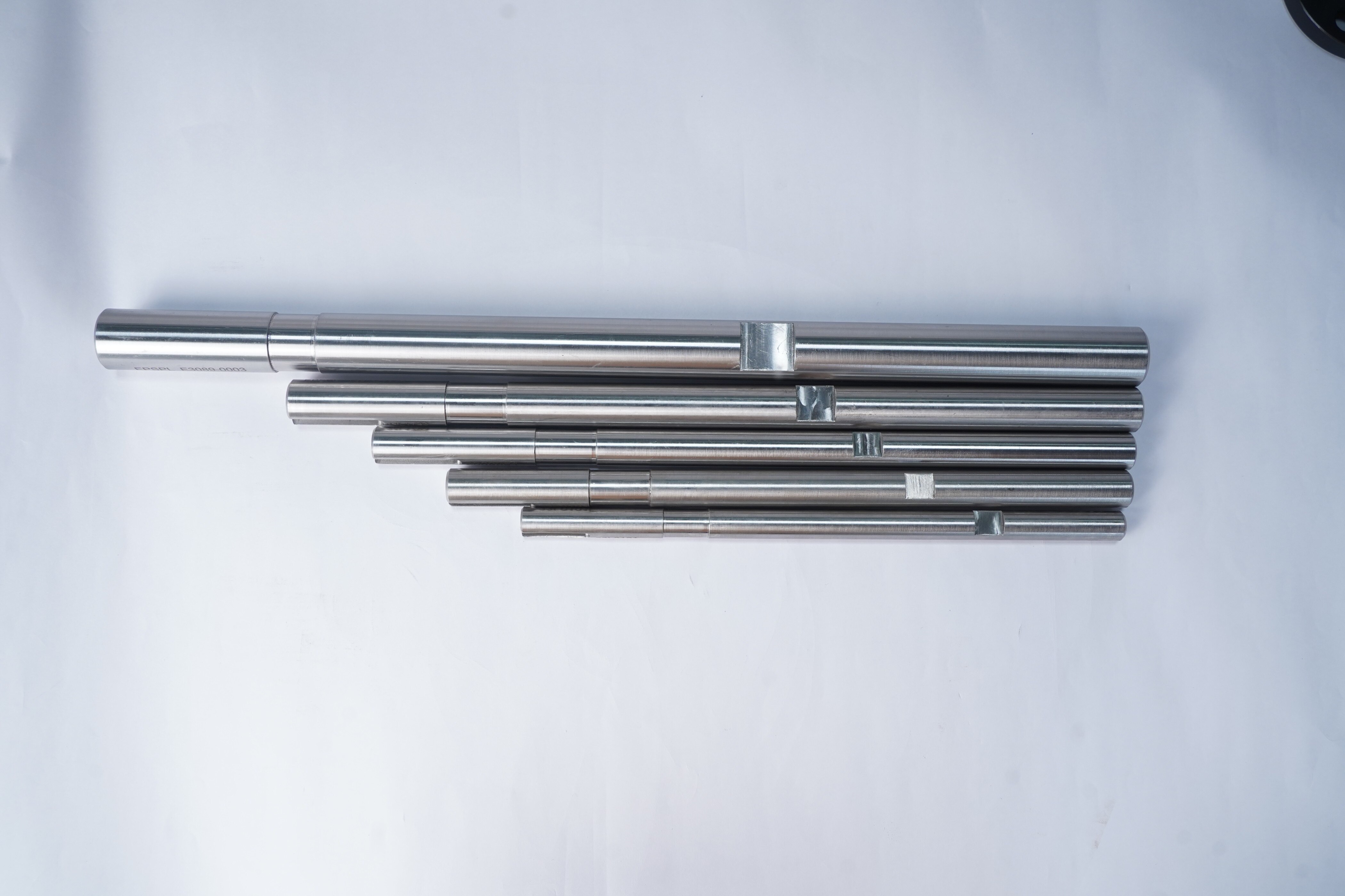
A valve stem is not one uniform shaft: its sealing journal, body-guide diameter and actuator interface perform different jobs and need separate drawing controls. A slight runout at the packing journal can cause uneven compression and leakage; a small diameter error at the actuator end may prevent torque transfer.
| Valve term or design | Functional zones and geometry |
|---|---|
| Stem or spindle in a gate or globe valve | Packing or bellows journal, guide diameter, threaded or T-head end, shoulder and anti-blowout feature |
| Stem in a ball valve | Packing journal, body guide, drive flat or square, shoulder and retainer groove |
| Shaft in a butterfly valve | Upper and lower guide diameters, disc-driving flats, cross-hole or keyway, sealing and retention shoulders |
| Actuator shaft | Coupling bore, keyway, square or splined interface; it transmits torque but is not the pressure boundary stem |
Specify straightness, concentricity, datum references and surface finish by zone. Measure a slender shaft between centres, in V-blocks or freely only when the method matches the drawing; each support condition can produce a different result.
Select the alloy from pressure, temperature, corrosion, media and required strength—not from valve name alone.
| Material | Use and limitation |
|---|---|
| 316 stainless steel | General corrosion resistance; verify chloride and temperature exposure |
| 17-4 PH stainless steel | Higher strength and wear resistance after heat treatment; check corrosion and hardness limits |
| Carbon or alloy steel | High strength in compatible, non-corrosive service; requires protection against corrosion |
| Brass | Low-friction service with compatible media; unsuitable for many high-pressure or corrosive duties |
| Nickel alloy | Severe corrosion or high-temperature service; higher cost and harder machining |
ASME B16.34 sets covered valve requirements such as pressure-temperature ratings and materials, not every stem diameter or journal finish. ISO 15848 fugitive-emission compliance belongs to the tested valve, packing or bellows and actuator assembly, not the shaft alone.
Choosing Swiss Turning, CNC Milling, Grinding or Thread Rolling
For a long, small-diameter valve stem with several features, Swiss-type sliding-head turning is usually the strongest primary choice. A guide bushing supports the bar beside the cutting tool, limiting deflection during turning and driven-tool work. This suits packing journals, guide diameters, shoulders, grooves, cross-holes, flats, slots and actuator-interface features on one setup.
| Process | Best use | Main limitation |
|---|---|---|
| Swiss turning | Long, slender stems and multiple turned or driven-tool features | Poor control follows if guide-bushing clearance, tool pressure or cutoff support is wrong |
| CNC milling | Flats, keyways, slots, off-centre holes and complex end features | A long unsupported shaft can deflect and lose positional accuracy |
| Grinding | Final sizing, roundness and surface finish on sealing or bearing journals | Adds handling and setup time; it does not replace feature machining |
| Thread rolling | Strong external threads with improved fatigue resistance | Requires suitable material, diameter allowance and thread geometry |
Use a subspindle or pickoff to finish the rear end without another chucking operation. This reduces datum transfer and concentricity error, but inspect features made on both spindles.
A practical industrial valve shaft manufacturing route is rough turning, finish turning, driven-tool work, thread machining, part-off or transfer, deburring, cleaning and inspection. Grind a journal after heat treatment when its finish or size demands it; expect higher tool wear and tighter distortion control.
Specify each process from the drawing, not from ASME B16.34 alone. That standard covers valve ratings, materials, dimensions and testing, while journal finish, thread tolerance and machining sequence remain application-specific.
Tolerances and Inspection That Protect Valve Operation
A shaft can meet its nominal diameter and still bind, leak or lose actuator torque. Control each functional zone separately: the packing journal seals, guide diameters align the stem, shoulders set axial position, and the actuator interface transmits torque.
| Feature | Failure if wrong | Inspection that matters |
|---|---|---|
| Packing or bellows journal | Leakage or accelerated packing wear | Micrometer or air gauge for diameter; roundness, cylindricity, runout and profilometer readings for the specified finish |
| Body-guide diameters | Binding, side load or stem misalignment | Diameter, straightness and total runout against drawing datums |
| Shoulders, grooves and tip length | Incorrect axial seating or anti-blowout engagement | Calibrated height gauge, CMM or optical measurement for location and length |
| Key, square, flat, pin hole or thread | Lost torque, backlash or assembly refusal | Width, across-flats, hole position, thread plug/ring gauges and flank inspection |
| Actuator mounting | Poor fit despite a “matching” shaft | ISO 5211 interface dimensions plus the drawing’s extension, key and tolerance stack |
Specify geometric controls under ISO 1101. A CMM result has meaning only when the drawing defines datums, so it cannot replace a datum-based requirement for coaxiality, straightness or total runout.
Require inspection records that identify the part batch, gauges used and calibration status. Check the material certificate and heat-treatment condition before release, then verify deburring and cleaning; a burr at a keyway or abrasive residue at a packing journal can defeat accurate dimensional results.
API 624 test evidence applies to the tested valve, packing and cycle conditions—not to stem dimensions alone.
How to Qualify a Valve Shaft Manufacturing Supplier
A supplier qualifies on evidence tied to your drawing, alloy and service conditions, not on location or a search result for “valve shaft supplier mannheim” or “precision machined shafts germany.” Request a production sample or first-article dossier before approving repeat batches.
1. Ask for drawing-review comments that identify the sealing journal, guide diameter, datums, actuator interface, threads and surface-finish requirements separately. A generic “shaft tolerance” response signals weak process control.
2. Request the material certificate to EN 10204 3.1, including heat or cast number, grade and chemistry. Match it to the batch label and ask for heat-treatment records when the drawing specifies 17-4 PH ageing, hardening or stress relief.
3. Request inspection results for diameter, straightness, concentricity, thread gauges and roughness. The report must state whether the shaft was measured between centres, in V-blocks or freely; each setup can produce a different result on a slender part.
4. Ask for evidence of capability on your length-to-diameter ratio, tightest tolerance and sealing finish: recent anonymised inspection reports, gauge calibration certificates and a control plan are useful proof.
5. Specify cleaning, burr removal, packaging and contamination limits, then request the signed release record and batch traceability from raw material to shipment.
6. If the supplier cites API 624 or ISO 15848, request the tested valve configuration, packing or bellows, temperature, cycle count and leakage result. Those standards qualify an assembly, not a bare stem.
Efficient Precision & System Pvt.Ltd should be compared using this same evidence, rather than its geography or manufacturing claims. A Mannheim address does not prove pressure-equipment conformity or fugitive-emission performance.
Related product
 | Industrial Valve Shaft If you're looking for the highest quality shafts in india and Germany , Efficient Precision is your place. |
Frequently asked questions
What is the manufacturing sequence for an industrial valve shaft?
The sequence runs from drawing and material review through turning, milling, grinding or rolling, heat treatment where specified, and final inspection.
How do you choose between Swiss turning, CNC milling, grinding and thread rolling?
Choose the process according to the feature: Swiss turning suits slender rotational profiles, milling creates flats and keyways, grinding controls critical diameters, and thread rolling forms strong external threads.
Which valve shaft dimensions require inspection?
Inspect sealing journals, guide diameters, shoulders, threads, keyways, cross-holes, actuator interfaces, surface finish, straightness and runout against the drawing.
How do you qualify a valve shaft manufacturing supplier?
Check its ability to interpret drawings, control material and heat treatment, machine slender features, document measurements and maintain repeatable process control.