
A bracket adaptor must preserve the valve-to-actuator interface while carrying torque, vibration, misalignment forces and environmental loads. By the end, you will know which dimensions and standards to request, how to specify materials and tolerances, and what evidence to require before accepting a custom part.
Key takeaways
- Check flange patterns, stem alignment and actuator clearances before fabrication.
- Specify material, corrosion protection and load requirements for the operating environment.
- Inspect fasteners, welds, alignment and movement after installation.
- Require drawings, material certificates, inspection records and dimensional results from the supplier.
What a bracket adaptor does in an installed valve assembly
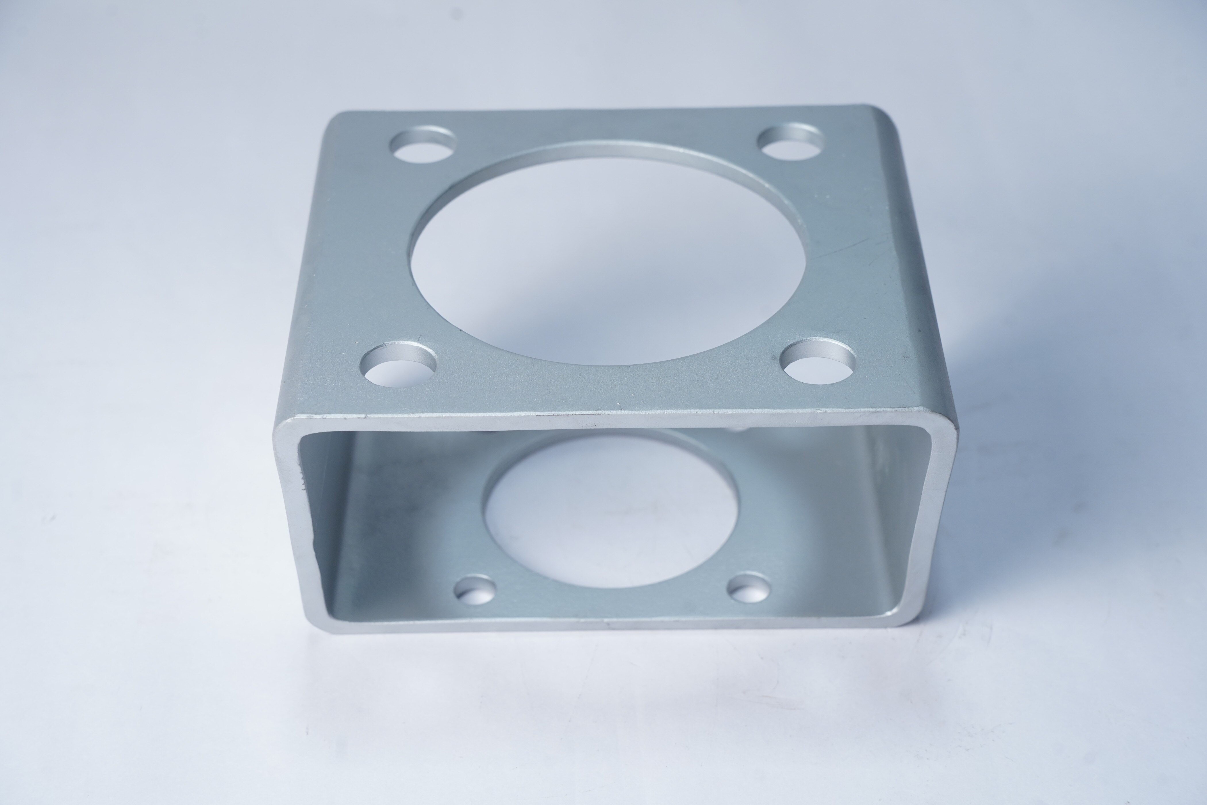
A bracket adaptor is the structural link between a valve body or valve mounting flange and an actuator flange. It transfers actuator reaction torque and mounting loads, while carrying forces caused by stem eccentricity, connected piping, vibration, shock and the actuator’s weight. Its geometry keeps the actuator correctly positioned around the stem or drive.
Use the name that matches the part’s actual function:
| Part | Physical role | Pressure-boundary status |
|---|---|---|
| Actuator-mounting spacer | Adds distance between actuator and valve | External-load part unless specifically designed otherwise |
| Valve mounting bracket | Supports and positions the actuator on the valve | Not automatically pressure-retaining |
| Stem adaptor or coupling | Transmits actuator drive through the stem | Usually separate from the structural bracket |
| Bracket adaptor | Establishes the structural and positional connection around the drive | Specify whether it sees external loads or pressure |
| Pressure-retaining component | Contains process pressure as part of the valve pressure boundary | Requires the applicable pressure-equipment design basis |
“Bracket adaptors for valve equipment Mannheim” describes a search, location, project or product family; Mannheim is not a dimensional standard. Bracket adaptors for industrial equipment must match the actual valve and actuator interfaces, including flange, pilot, bolt pattern and drive geometry. DN alone cannot define that fit.
A supplier specification must state whether the adaptor is only an actuator support, a spacer, or part of pressure equipment.
How to prove the valve and actuator will fit
Release an industrial valve bracket adaptor design only after obtaining the valve make, model, nominal size, pressure class, actuator type and revision-controlled valve and actuator drawings. Those documents, not “Mannheim” or DN alone, establish compatibility.
- Record the mounting-hole pattern, bolt-circle diameter, hole diameter and thread, flange standard, pilot diameter, stem shape and dimensions, key or square size, actuator output size, shaft engagement length, adaptor thickness and available clearance.
- For a quarter-turn assembly, compare the actuator flange designation and drive dimensions with ISO 5211. Use ISO 5210 for a linear actuator interface. Where the adaptor meets a flanged valve, check EN 1092-1 or ASME B16.5 as applicable.
| Interface | Controlling reference | Compatibility decision |
|---|---|---|
| Quarter-turn actuator | ISO 5211 | Match flange designation, pilot, bolt pattern and drive |
| Linear actuator | ISO 5210 | Match the linear attachment and output interface |
| Flanged valve | EN 1092-1 or ASME B16.5 | Match the actual flange, not nominal size alone |
Put functional datums and individual tolerances on the drawing for hole location, coaxiality, concentricity, face relationship and drive engagement. Overall dimensions and ISO 2768-style general tolerances cannot control these interfaces. Specify tool access, minimum wall thickness, deburring and surface finish, especially for custom valve bracket components with thin webs, deep bores or locating faces.
The shaft must engage fully without bottoming, and the adaptor must leave enough clearance for fasteners, tools and actuator travel.
How service conditions change the adaptor design
A robust industrial valve bracket adaptor is designed from combined loads and failure modes, not actuator nameplate torque alone. The same rule applies to custom valve bracket components: calculate the worst operating case before fixing geometry or material.
- Calculate actuator reaction torque, breakaway torque, stem-side eccentricity, pipe-induced forces and moments, seismic or transport loads, vibration and cyclic fatigue. A static-torque pass can still end in bolt slip, local bearing failure or fatigue.
- Design the bolted joint for preload, separation and slip resistance. Check friction coefficient, hole clearance, embedment, washer geometry, thread engagement and preload scatter; bolt tensile strength alone does not prove that the joint will resist slip.
- Check local bearing and stress concentration at internal corners, then assess fatigue at thin webs and deep bores. Include weld fatigue wherever the adaptor is welded. A sharp corner can fail long before the gross section reaches its nominal strength.
- Match the material to the failure mode and environment. For carbon steel, specify an ISO 12944 coating system with preparation grade, dry-film thickness, edge treatment and machined-face masking. For 1.4301/304 or 1.4404/316L, review chloride pitting, galvanic contact and stress-corrosion cracking.
Match the material certificate, product form, heat treatment and impact-toughness requirement to the minimum design temperature. State controls for sour gas, wet-dry cycling and elevated temperature, and assess low-temperature fracture rather than relying on room-temperature strength.
How to install and inspect the assembly without creating hidden failure
A correctly machined adaptor can fail during installation if misalignment is forced into the joint. Clean both mounting faces, verify the pilot diameter and drive dimensions, and confirm that the valve and actuator axes are coaxial before tightening.
Never pull an offset actuator into position with fasteners; that creates stem binding, uneven bolt loading and lost actuator travel.
Use the specified bolt grade, washer arrangement, thread engagement and tightening sequence. Record the torque value or preload method. Check full shaft engagement without bottoming, rotate the assembly manually or by test through the required travel, and confirm unobstructed clearance around the adaptor.
On receipt, inspect:
- The material certificate, heat or cast number, dimensional report and hole pattern.
- Face flatness, thread condition, coating damage and the passivation record where applicable.
For bracket adaptors for industrial equipment, compare inspection in both conditions:
| Inspection condition | Check | Failure exposed |
|---|---|---|
| Free state | Flatness, hole locations and drive dimensions | Machining error or released-part distortion |
| Clamped state | Alignment, face contact and axis relationship | Workholding or installation distortion |
Retain alignment measurements, bolt-tightening records, travel verification and every nonconformance disposition. A thin or multi-axis adaptor that passes free-state inspection can still distort under its intended clamp load.
How to qualify a supplier and define the acceptance package
A search label is not supplier evidence: “valve bracket adaptor manufacturer Germany” does not prove German manufacture, ISO 9001 certification, or competence. Verify the factory address, ISO 9001 scope, material-control system, calibration records, inspection equipment, and whether coating or heat treatment is subcontracted.
Compare suppliers against evidence, not claims:
- Request a revision-controlled drawing, valve and actuator interface measurements, critical-datum results, and a first-article or complete dimensional report.
- Require material and heat-treatment certificates identifying grade, product form, heat or cast number, and EN 10204 inspection-document type.
- Specify coating dry-film thickness records or passivation records, where applicable.
- Define traceability, nonconformance approval, rework authority, and deviation-disposition procedure before production starts.
| Evidence | Acceptable proof | Warning sign |
|---|---|---|
| Manufacturing | Named production site and process route | Search wording or sales-office address only |
| Quality system | ISO 9001 certificate with machining and inspection in scope | Certificate with unrelated or unclear scope |
| Special processes | Approved subcontractor records for coating or heat treatment | “Customer-approved suppliers” without records |
| Inspection | Calibrated equipment and reported critical datums | Generic certificate of conformity |
For custom valve bracket components, assign conformity responsibility across the valve, actuator, adaptor, and completed equipment. The EU Pressure Equipment Directive and EU Machinery Regulation do not automatically apply to every loose adaptor; applicability depends on its function in the assembled equipment.
Efficient Precision & System Pvt.Ltd belongs in a Mannheim-area review only through the same evidence: ask what machining, inspection, traceability, and subcontract-process records accompany the specific design. “bracket adaptors for valve equipment Mannheim” describes a search, not a standard.
Related product
 | Industrial Valve Efficient Precision and System Pvt. Ltd. is a leading supplier, exporter and manufacturer of Valve Brackets based in India. View product → |
Frequently asked questions
What does a bracket adaptor do in a valve assembly?
It links the valve mounting flange to the actuator flange and transfers reaction torque, mounting loads, vibration, shock and actuator weight while keeping the actuator aligned with the stem or drive.
How do you prove a valve and actuator will fit?
Compare the valve and actuator flange patterns, bolt sizes, pilot diameters, stem or drive dimensions, centreline height, rotation direction and available clearances before manufacturing the adaptor.
How do operating conditions affect bracket adaptor design?
Temperature, corrosion, vibration, shock, actuator weight, reaction torque and piping loads determine the adaptor material, section thickness, fasteners, surface protection and inspection requirements.
What should you inspect during bracket adaptor installation?
Check flange contact, bolt engagement and tightening, stem alignment, actuator position, welds, coating damage, clearances and free operation so installation does not create hidden loading or misalignment.
What documents should a bracket adaptor supplier provide?
Request an approved drawing, material certificates, coating or heat-treatment records, dimensional inspection results, weld documentation where applicable, fastener details and a final conformity statement.