
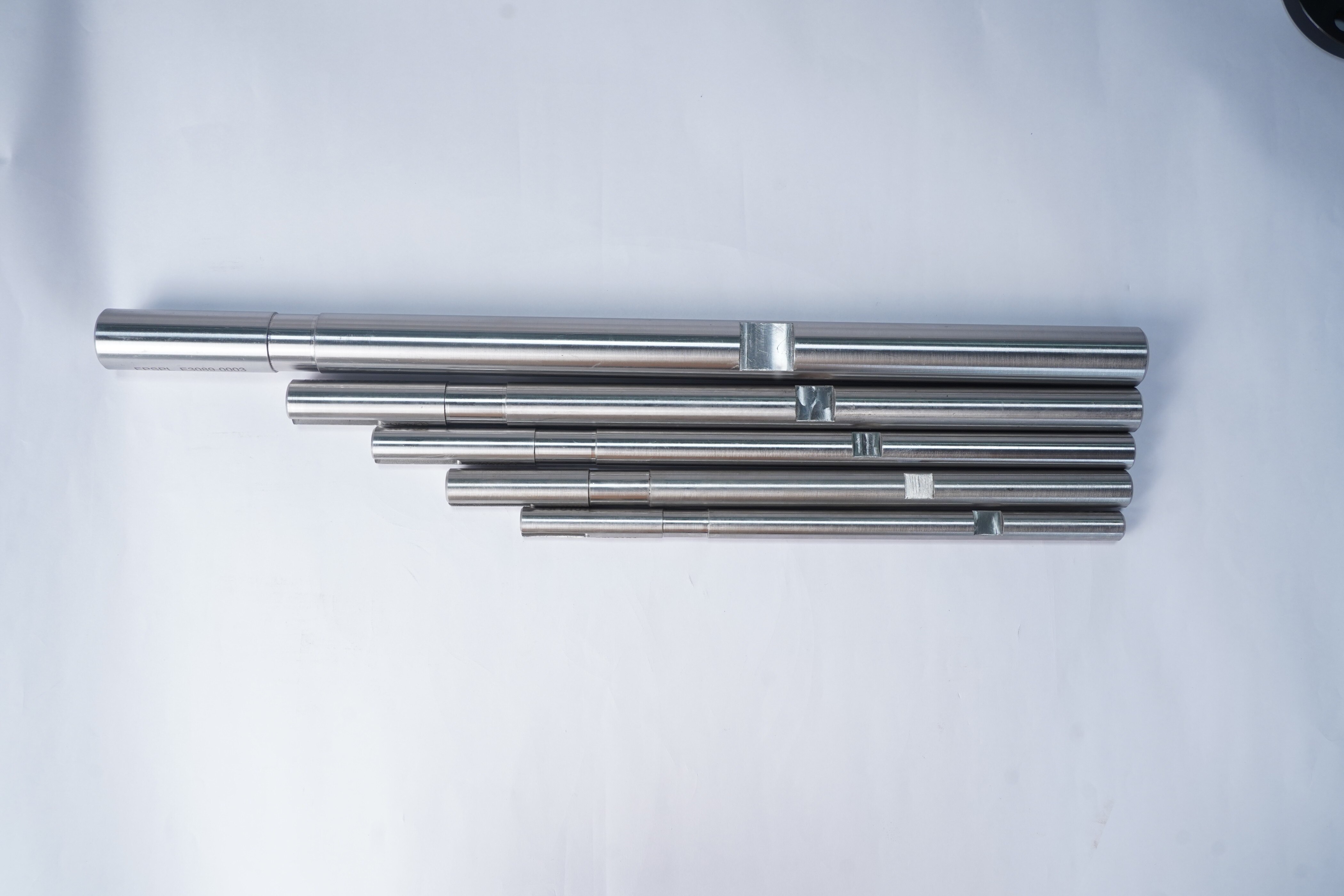
A valve shaft is a load-bearing, sealing and torque-transmitting component, not a generic round bar. To order the correct part, you need to define its function, interface geometry, material condition and inspection method as one working system.
Key takeaways
- Define torque, thrust, stroke, runout and sealing surfaces before requesting quotes.
- Match shaft material and heat treatment to corrosion, temperature and wear exposure.
- Control shaft-to-bore fits, surface finish and runout at the assembled sealing location.
- Compare suppliers by inspection records, traceability, machining capability and repeatability.
What a shaft does inside a valve mechanism
A valve mechanism shaft converts handwheel or actuator torque into movement while carrying axial thrust, sealing loads and contact forces. A stem lifts a gate or globe plug; a valve shaft rotates a disc, ball or plug; both must support the closure element and maintain alignment through guides, packing, bellows or rotating seals.
Name the component precisely before requesting shafts for industrial equipment valve mechanisms:
| Name | Primary function | Typical interface |
|---|---|---|
| Valve stem | Transmits torque or axial movement to the closure element | Packing, bellows, bonnet guide, handwheel or actuator |
| Valve shaft | Rotates a disc, ball or plug | Bearings, bushings and seal tracks |
| Actuator shaft | Transfers actuator output | ISO 5211 mounting and drive connection |
| Drive shaft | Couples separate drive components | Key, spline, flat or coupling |
| Spindle shaft | Usually provides controlled linear movement | Thread, nut and guide |
| Hinge shaft | Supports pivoting movement | Disc or lever hinge and bushings |
A stem passing through packing or a bellows seal cannot be specified by diameter alone. Define the sealing diameter, bonnet guide, stem shoulder, thread, actuator connection and allowable runout together; helical tool marks or a shoulder burr can increase leakage and operating torque.
API 600, API 602 and API 623 cover different steel gate and globe-valve frameworks, not one interchangeable stem geometry. ISO 5211 defines part-turn actuator and valve mounting interfaces, but not stem material, sealing diameter or guide diameter. Identify these loads and interfaces before seeking a quote.
How to specify shaft geometry and the mating parts
Turn the sample into a controlled geometry record, not a list of outside diameters. State overall length, assembly axis, datum faces, stepped diameters, shoulder locations and every feature that locates, seals, retains or drives the shaft.
Record these features on the drawing:
- Keyways, D-flats, splines and cross-drilled holes, with size, position and orientation
- External and internal threads, reliefs, grooves and snap-ring grooves
- Packing diameters, O-ring grooves, lip-seal tracks, bearing or bushing journals and retainer-ring locations
- Actuator coupling dimensions, including the ISO 5211 mounting interface where applicable; ISO 5211 does not define the stem’s sealing diameter, guide, thread or runout
Choose the shaft form against the actual mating part and load:
| Option | Torque and weight | Machining and coupling |
|---|---|---|
| Solid | Highest material reserve; heaviest | Simplest, with maximum keyway and seal support |
| Hollow | Lower weight and inertia | More machining; less wall around keys, threads and seals |
| Stepped | Places journals and seals accurately | Extra shoulders and turning operations |
| Keyed | Practical for moderate torque | Simple hub, but stress concentration and assembly clearance |
| Splined | High torque density and positive indexing | Costlier broaching or milling; tighter coupling control |
| D-flat | Low torque to moderate torque | Fast, economical machining; simple clamp or actuator hub |
A sample alone cannot establish function. Mark the datum faces, critical shoulder positions and the features that establish the assembly axis, then dimension mating clearances, seal tracks and actuator engagement from those references. A keyed connection is simpler than a spline for low-cycle service; choose a D-flat when reducing machining matters more than torque capacity.
How material, environment and heat treatment change the design
Choose the shaft for its service, not its material name. Fluid temperature and pressure, abrasive particles, washdown chemicals, corrosion, cycling frequency and seal friction determine the useful combination of strength, toughness, wear resistance and corrosion resistance.
| Material | Main advantage | Use when |
|---|---|---|
| 316 stainless steel | General corrosion resistance | The fluid and washdown environment are corrosive but strength demands are moderate |
| 17-4 PH stainless steel | Higher strength after precipitation hardening | Specify the condition and aging treatment for a defined strength requirement |
| Carbon steel | Economical strength and machinability | The environment is controlled and corrosion protection is reliable |
| Duplex stainless steel | High strength and chloride resistance | Chloride exposure makes pitting or stress-corrosion cracking a concern |
| Nickel alloy | Severe corrosion and temperature resistance | Hot, aggressive fluids exceed stainless-steel capability |
| Hardened tool steel | High wear resistance | Abrasive particles or repeated contact dominate service life |
“17-4 stainless” is incomplete. State the condition, aging treatment, required hardness or tensile strength, operating temperature and corrosion environment; the wrong aging cycle can leave the shaft too soft, too brittle or unsuitable for the fluid.
Hardening after turning can change diameter, size and straightness. Leave distortion allowance on slender parts, then finish journals and sealing diameters by grinding, hard turning or superfinishing.
Thread manufacture also changes the design. Rolled threads need suitable material, blank diameter, thread length, relief geometry and tool access, while cut threads suit short runs, difficult materials, internal shoulders or unrollable shapes. A rolled thread can retain grain flow and improve fatigue performance; a cut thread offers greater geometric flexibility.
How to verify fit, runout and sealing performance
Approve a shaft against the drawing by checking size, geometry and surface function from a defined datum axis—not by measuring outside diameters alone. ISO 286-1 defines limits and fits for size; ISO 1101 defines geometric tolerances, so a shaft within its diameter tolerance can still fail for straightness, cylindricity, coaxiality or runout.
1. Establish the datum axis from the bearing or primary journal identified on the drawing. Record whether each requirement is radial runout or total runout, then inspect the packing diameter and actuator interface at the stated locations. For a slender stem, total runout at these functional surfaces is more useful than an unqualified “concentric” note.
2. Check straightness, roundness or cylindricity, journal-to-thread runout and shoulder perpendicularity using the agreed setup. A slender part can produce different results on V-blocks, between centres or in a rotating fixture, so approve the method before production.
3. Verify thread form, pitch, major and minor diameters, flank condition and engagement length. Inspect keyways, flats, grooves and cross-holes when they establish the mating position.
4. Inspect packing and sliding surfaces for the specified texture under ISO 21920-1. State the surface, Ra or other parameter, lay restriction and measurement method; one Ra value cannot describe every sealing surface.
5. Reject helical tool marks, torn metal, shoulder burrs and damaged transitions. They cut packing, increase leakage and raise operating torque despite an acceptable diameter.
An EN 10204 certificate records inspection conformity at the stated certification level. It does not replace geometry, surface texture or heat-treatment requirements; list the characteristics and certificate type you require.
How to compare a shaft supplier before placing the order
Compare evidence, not a quoted maximum machine length. Ask every supplier to review your drawing and confirm how it will control the functional features of a small, long or integrated valve shaft.
| Supplier evidence | What to request | Why it matters |
|---|---|---|
| Material and heat treatment | Material condition, heat-treatment route, hardness, and allowance for distortion | Slender shafts can change size and straightness after hardening |
| Finishing | Grinding, hard turning or superfinishing method for journals and sealing diameters | Turning alone may leave leakage-producing texture or taper |
| Datums and inspection | Datum axis, inspection locations, radial or total runout, and equipment used | “Concentric” alone does not define an acceptance test |
| Threads and certificates | Rolled or cut thread method, plus the EN 10204 certificate type | The thread process affects strength; a certificate does not prove geometry |
| Inspection report | Exact recorded characteristics, including straightness, roundness, cylindricity, thread form, hardness and surface texture | A diameter-only report can miss assembly failure |
For slender shafts, demand results at the packing diameter and actuator interface. A sliding-head Swiss-type machine uses a guide bushing near the cutting zone to reduce deflection, but bar straightness, bushing adjustment, thermal growth, tool wear and cutoff distortion still require control.
Use these checks when comparing suppliers:
- Request a drawing review, sample inspection plan and measurable acceptance criteria before production.
- Ask for demonstrated runout and straightness on a comparable diameter and length, not the machine’s advertised capacity.
- During a search for an industrial equipment shaft supplier düsseldorf, precision shafts for machinery germany, or a cnc shaft manufacturer, assess process evidence rather than location alone.
Efficient Precision & System Pvt.Ltd is relevant because its Düsseldorf operation combines sliding-head, CNC, VMC and multi-axis machining for tight-tolerance components.
Related product
 | Industrial Valve Shaft If you're looking for the highest quality shafts in india and Germany , Efficient Precision is your place. |
Frequently asked questions
What does a shaft do inside a valve mechanism?
A stem transfers actuator force into linear movement, while a valve shaft rotates a disc, ball or plug. Both carry alignment, thrust, sealing and contact loads.
What shaft dimensions should you include in a drawing or purchase specification?
State the shaft diameter, overall length, shoulders, keyways or flats, threads, retaining features, sealing diameters, tolerances, datum scheme, surface finish and mating-part dimensions.
How do material and heat treatment affect a valve mechanism shaft?
Choose the material for torque, temperature, corrosion and wear conditions. Heat treatment changes hardness, strength, dimensional stability and resistance to galling, so specify the required condition and verify it.
How do you verify shaft fit, runout and sealing performance?
Measure critical diameters with calibrated gauges, check fit against the mating bore, measure total indicated runout at the sealing and bearing surfaces, and test leakage with the specified packing, bellows or rotating seal.
How should you compare a shaft supplier before ordering?
Check drawing review, CNC process capability, material certificates, heat-treatment records, first-article inspection, traceability, measurement equipment, packaging and evidence of repeatable production.