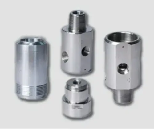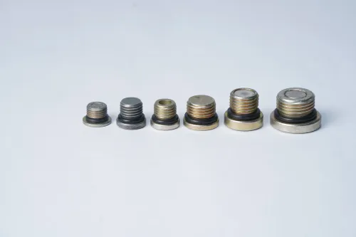

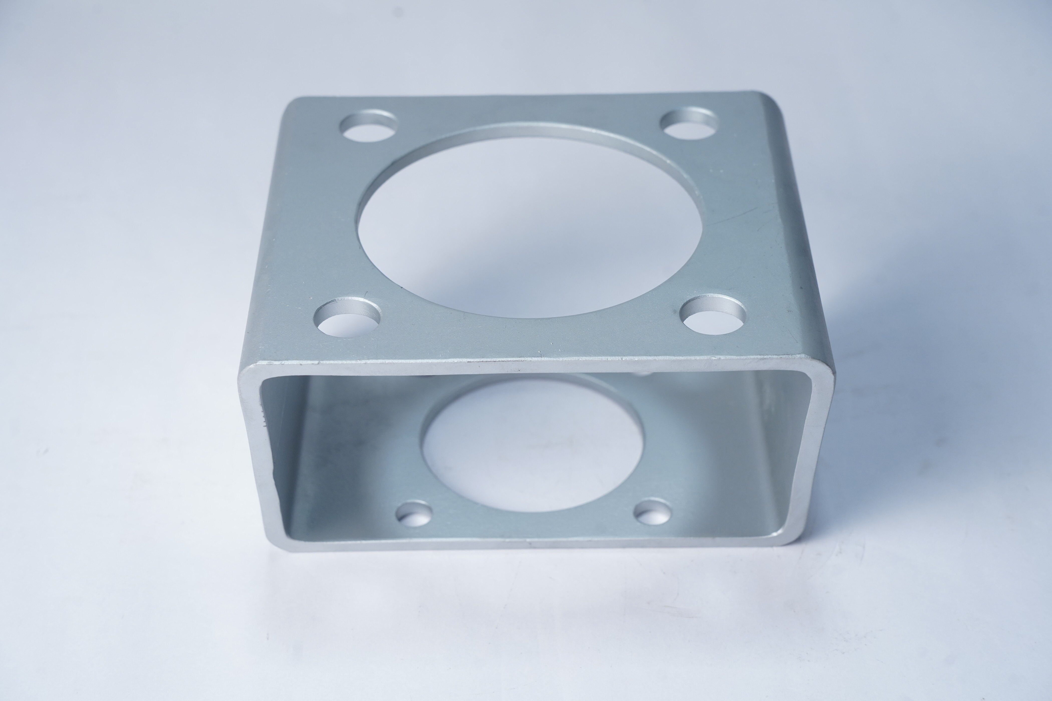
A bracket adaptor must do more than connect two bolt patterns: it has to preserve shaft alignment, transmit the governing actuator torque and survive the valve’s environment. By the end, you will be able to distinguish the available bracket types, specify the interface and materials, and test whether a Düsseldorf-area manufacturer or another supplier has provided enough evidence for a reliable fit.
Key takeaways
- Match the adaptor to the valve face, actuator pattern, stem axis and torque.
- Confirm torque, loads, clearances and fail-safe movement before approving dimensions.
- Choose stainless steel or coated steel by fluid, temperature and corrosion exposure.
- Inspect hole position, parallelism, concentricity and traceable machining records.
What a valve bracket adaptor connects—and which valves use it
A bracket adaptor is the engineered interface between a valve’s mounting face and an actuator’s mounting pattern, transmitting actuator torque to the valve stem while keeping both axes aligned.
It is usually a torque and alignment component, not part of the pressure boundary; the valve’s pressure, temperature and leakage ratings do not automatically apply to the adaptor.
The industrial valve bracket adaptor benefits are application-dependent: it can convert mismatched interfaces, simplify actuator replacement and standardise one actuator arrangement across several valve families. It also adds height, fasteners, tolerance accumulation, corrosion interfaces and another torque-transmission joint to inspect.
| Component | What it connects or supports | Main distinction |
|---|---|---|
| Bracket adaptor | Valve to actuator or mounting bracket | Converts interfaces and transmits torque |
| Actuator mounting bracket | Actuator to valve body or support structure | Provides the primary actuator stand-off and load path |
| ISO 5211 mounting plate | Part-turn valve to actuator interface | Defines standard flange and drive dimensions; it is not automatically a complete adaptor |
| Valve support bracket | Valve or pipework to a frame or equipment structure | Carries weight and piping loads, not actuator torque |
Ball and butterfly valves commonly use this arrangement because they need quarter-turn actuation. Gate, globe and diaphragm valves use adaptors when their actuator connection, stem arrangement or travel mechanism requires one; their linear thrust demands a different design from a simple part-turn plate.
Check stem engagement, shaft diameter and height, bolt spacing, clearance and required rotation before treating any adaptor as universal.
Specify the valve, actuator and torque envelope before ordering
A fit claim means little without the valve’s actual interface drawing and the actuator model. Give the valve bracket adaptor supplier the valve flange designation under ISO 5211, actuator mounting pattern, stem or drive dimensions, required rotation and total assembly height. Use VDI/VDE 3845 dimensions for a pneumatic actuator interface where applicable.
| Specification | Evidence to request | Failure prevented |
|---|---|---|
| Valve interface | ISO 5211 flange designation, drive-square or key dimensions, stem diameter and height | An adaptor that bolts on but leaves insufficient stem engagement |
| Actuator interface | Actuator model, flange drawing, bolt-circle diameter, hole size and bolt grade | Misaligned holes, undersized fasteners or inaccessible bolts |
| Torque envelope | Breakaway, running, seating, emergency and abnormal torque values | Joint slip or adaptor distortion during the highest load |
| Geometry | Mounting-face flatness, perpendicularity, concentricity and critical GD&T | Eccentric loading, backlash and excessive actuator wear |
| Operating movement | Required 90-degree or other rotation, mechanical stops and clearance | A valve that reaches neither full open nor full closed |
| Verification | ISO 5211 and VDI/VDE 3845 references, inspection report and material certificate | Compatibility claims that cannot be checked |
Size the drive component, anti-rotation features and fasteners for the governing torque, not normal running torque; require the supplier to state the safety margin and calculation basis. Check that the valve’s pressure, temperature and leakage ratings do not get incorrectly assigned to the adaptor, which is normally outside the pressure boundary.
- Confirm the adaptor drawing shows bolt access, actuator-removal clearance and stack height.
- Require dimensional inspection of the flange, holes, shaft engagement and critical GD&T before approval.
Choose material and finish for the actual service environment
Select the adaptor material against the fluid, atmosphere, cleaning chemicals and temperature at the installation, not against machinability alone. Carbon steel beside a stainless-steel valve can create a galvanic corrosion point, especially with salt water or condensation; isolate the metals or specify a compatible stainless grade.
| Material and finish | What it means | When it applies |
|---|---|---|
| Carbon steel with suitable coating | High stiffness and economical machining; coating damage exposes steel | Dry indoor service, or where chemical and temperature ratings suit the coating |
| 304 or 316 stainless steel, passivated | Corrosion resistance without a separate film; 316 suits chloride exposure better than 304 | Washdown, humid areas and corrosive atmospheres |
| Plated or coated steel | Adds a barrier, but scratches, edge coverage and adhesion control service life | Controlled environments where the finish supplier states chemical and temperature limits |
| Electropolished stainless steel | Smooths and cleans the surface; removes material from critical features | Hygienic or contamination-sensitive service, after dimensional review |
Treat the finish as a dimensional operation. Passivation has little dimensional effect, while plating, coating and electropolishing can alter bores, pilots and threaded holes; inspect those features after finishing. Set operating limits from the coating temperature and chemical data, plus the actuator’s breakaway, running, seating and emergency torque.
A finish cannot compensate for an adaptor that flexes or fasteners that fall below the governing torque margin. Capture the material grade, finish specification, temperature range and inspection results in the purchase record.
Judge machining quality, geometric control and Düsseldorf provenance
A German postcode or the phrase “bracket adaptor manufacturer Germany” does not prove where machining occurred. Ask for the plant address, machining-site legal entity, inspection location and subcontractor records for heat treatment or coating; a Düsseldorf office can sell a part made elsewhere.
Request a qualification pack containing:
- The valve and actuator model, interface drawing, ISO 5211 flange designation and VDI/VDE 3845 dimensions where applicable.
- A controlled drawing showing pilot diameter, bolt circle, hole position, stem bore, key or square orientation, engagement depth, stack height and critical GD&T.
- Material certificates to EN 10204 3.1, linked to the production lot, plus coating or heat-treatment certificates when those operations are outsourced.
- First-article or in-process inspection results from a calibrated CMM, with measured bore, bolt pattern, parallelism, perpendicularity and concentricity against drawing tolerances.
- A batch number connecting raw material, machining route, inspection report and shipped quantity.
ISO 5211 identifies the actuator-to-valve attachment interface and reference torque values; it does not define every valve stem or drive bore. A supplier claiming universal compatibility without those dimensions is avoiding the fit-critical work.
For Efficient Precision & System Pvt.Ltd, ask whether the quoted bracket adaptor is machined at the stated German site or supplied through another facility. An industrial valve bracket adaptor manufacturer for Düsseldorf earns provenance through traceable records, not search ranking, while accurate geometry is demonstrated by controlled drawings and measured results.
Related product
 | Industrial Valve Efficient Precision and System Pvt. Ltd. is a leading supplier, exporter and manufacturer of Valve Brackets based in India. View product → |
Compare the benefits with the extra joint in the assembly
Use an adaptor when it solves a defined interface problem: it can let you pair a separately supplied valve and actuator, replace an actuator without reworking the valve, or standardise one actuator arrangement across valve families. It earns its place when alignment, stem engagement and torque transfer remain controlled after installation.
| Situation | Benefit | Added burden |
|---|---|---|
| Separate valve and actuator supply | Converts mismatched mounting interfaces | Adds fasteners, stack height and a second tolerance loop |
| Actuator replacement | Preserves the existing valve and simplifies change-out | Check removal clearance, bolt access and stem engagement |
| Several valve families | Standardises one actuator pattern | Confirm each valve’s flange, pilot and drive dimensions |
| Direct-compatible valve and actuator | No adaptor joint or interface conversion | Usually the simpler, lower-inspection choice |
Choose the direct connection when it fits the valve’s ISO 5211 flange and drive without forcing eccentric loading, excessive backlash or an over-height assembly. An adaptor’s benefit disappears when the added height blocks pipework or handwheel access, prevents actuator removal, or leaves too little engagement on the valve stem.
Inspect the adaptor joint as a torque-transmission connection, not as part of the pressure boundary. Check bolt torque, pilot seating, coaxiality, corrosion at mating faces and any movement during commissioning; the added joint creates another failure point and another record to maintain.
Reject the arrangement if the supplier cannot provide the assembled tolerance stack and inspection dimensions.
Frequently asked questions
What does a valve bracket adaptor connect?
It connects a valve mounting face to an actuator mounting pattern while transmitting torque and maintaining stem alignment.
What information should you provide before ordering an adaptor?
Provide the valve type, mounting dimensions, stem details, actuator pattern, torque requirements, travel limits and available clearances.
How do you choose a bracket adaptor material and finish?
Choose the material and finish from the fluid, temperature, humidity, corrosion exposure, cleaning method and installation location.
Which machining checks matter for a valve bracket adaptor?
Check mounting-hole position, face parallelism, stem-axis alignment, concentricity, thread quality and dimensional traceability.
What is the disadvantage of adding a bracket adaptor?
The adaptor adds a joint, parts and alignment work, so you must control fastener security, stiffness, clearance and maintenance access.