
A bracket adaptor creates the mechanical interface between a valve, its actuator and the supporting structure, while keeping the drive shaft or stem on the correct axis. By the end, you will be able to trace the torque or thrust path, identify the right interface dimensions, and spot fit errors that cause leakage, binding or actuator damage.
Key takeaways
- Use the adaptor to set shaft height, orientation, and concentricity.
- Match the valve mounting flange, stem geometry, and actuator interface before ordering.
- Control radial, axial, and torsional loads to prevent binding and uneven wear.
- Specify materials, tolerances, surface finish, and inspection requirements on the drawing.
How the adaptor transfers motion and supports the actuator
The adaptor creates the mechanical bridge between an actuator and a valve stem. It places the actuator output shaft at the correct height and orientation, then holds both axes concentric so the stem turns or moves without binding. It is an interface part, not normally a pressure-containing section of the valve.
The torque path runs from the actuator output through a stem adaptor or coupling and into the valve stem. The bracket carries the actuator’s reaction torque, while its bolts transfer that load into the valve body or mounting flange.
In a linear assembly, the equivalent hardware carries actuator thrust into a stem nut, yoke, or thrust adaptor rather than transmitting rotary torque.
The industrial valve bracket adaptor function includes three mechanical jobs:
- Maintain the required stem position while the actuator operates.
- Support the actuator’s weight and resist reaction forces.
- Keep the coupling aligned so torque reaches the stem instead of bending shafts or rubbing seals.
A valve adaptor component can also add clearance between the actuator and valve. That spacing prevents interference with a handwheel, positioner, insulation, or hot process piping, but excessive height increases bending load and vibration. A rigid-looking bracket can still loosen through bolt-hole fretting or distort under peak torque.
For multi-turn or linear equipment, use the correct thrust interface, such as a mounting adaptor, yoke, or stem nut. ISO 5210 governs many multi-turn actuator and valve attachment dimensions; an ISO 5211 quarter-turn adaptor does not replace that load path.
An undersized actuator remains undersized because the bracket only transfers force; it cannot create the breakaway or seating torque the valve requires.
Which valve and actuator arrangements use an adaptor
Quarter-turn ball and butterfly valves commonly use bracket adaptors with pneumatic or electric actuators. The valve-side interface usually follows ISO 5211, while a pneumatic actuator’s NAMUR/VDI-VDE 3845 interface mounts accessories on the actuator and is not the valve connection.
Multi-turn globe and gate valves use a mounting adaptor, yoke, stem nut, thrust adaptor or extension under ISO 5210 instead.
| Component | Mechanical job | Typical arrangement |
|---|---|---|
| Bracket adaptor | Holds the actuator, reacts torque and preserves alignment | Quarter-turn valve-to-actuator retrofit |
| Coupling | Transfers actuator rotation into the valve stem | Square, keyed, splined or slotted stem connection |
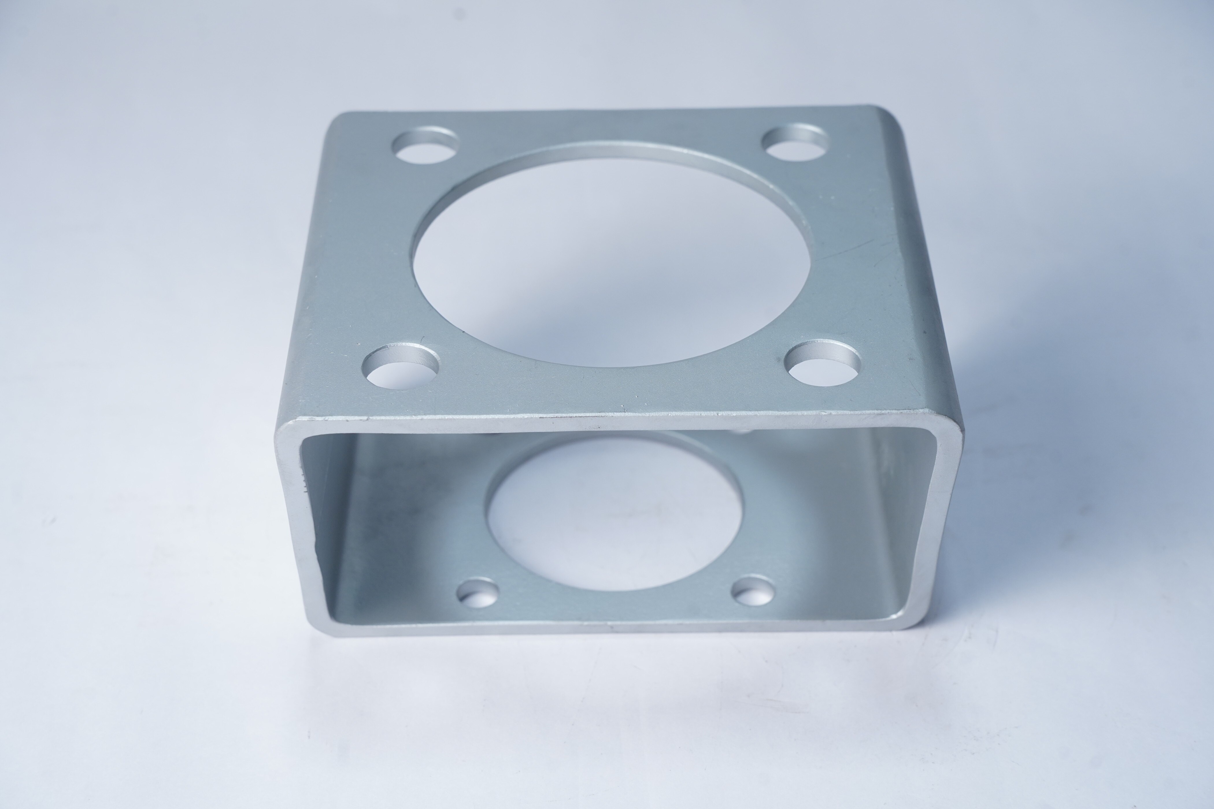
| Mounting bracket | Rigid support frame between equipment parts | Remote actuator mounting or offset installations |
| Mounting plate | Flat drilled interface for bolt patterns | Simple actuator-to-valve conversion |
| Stem extension | Moves the drive point away from the valve | Insulated, buried, hot or obstructed valves |
| Bonnet hardware | Retains and guides the valve stem or actuator load path | Globe and gate valves with linear or multi-turn drives |
Typical bracket adaptor applications include automating a manual quarter-turn valve, converting between mounting standards, and positioning an actuator away from heat or vibration. They also package valves with gearboxes, positioners, limit switches or solenoids.
Do not substitute a quarter-turn adaptor for a multi-turn thrust connection. In control-valve service, changing the coupling or extension stack-up can alter calibrated travel and the fail position, even when the bolts fit.
How to match the adaptor to the valve and actuator interfaces
A matching F-size is only the starting point. Check the valve flange, actuator flange, bolt-circle diameter, hole diameter, bolt size, stem height, shaft axis, drive shape, drive depth and available clearances. A correct pattern with the wrong stem geometry will mount securely but fail to transmit motion.
Use ISO 5211 for part-turn valve and actuator interfaces, including flange and drive dimensions. It does not guarantee compatibility: confirm the actual F-size, square or keyed stem, coupling engagement, torque direction and actuator rotation. NAMUR/VDI-VDE 3845 usually describes the actuator’s top accessory mounting interface, not its valve connection.
| Equipment arrangement | Interface to verify | Wrong choice causes |
|---|---|---|
| Quarter-turn ball or butterfly valve | ISO 5211 flange, stem profile, stem height and coupling depth | Partial rotation, slipping or excess stack height |
| Pneumatic actuator accessory | NAMUR/VDI-VDE 3845 hole spacing and shaft position | An adaptor that fits the actuator but not the valve |
| Multi-turn or linear valve | ISO 5210 mounting, thrust path, stem nut or yoke dimensions | Lost thrust, binding or damaged threads |
For multi-turn and linear equipment, specify ISO 5210 rather than substituting a quarter-turn adaptor. Include the required torque or thrust, actuator orientation, extension length and obstruction clearances. A buyer searching “how does a valve bracket adaptor for work düsseldorf” should provide these dimensions, not only the phrase “bracket adaptor.”
What alignment and loading errors do to valve operation
A coupling that sits a few degrees off-axis can make a correctly sized actuator struggle. The industrial valve bracket adaptor function depends on concentricity, parallel mounting faces, correct stem height and enough drive engagement. If the actuator shaft and valve stem do not share the intended axis, the coupling binds instead of transmitting clean torque.
- Incorrect geometry creates eccentric rotation, which loads actuator bearings and stem packing sideways. The valve can wear at the coupling, fail to reach its seating position and leak because the stem never completes its calibrated travel.
- Insufficient bracket strength allows local bending, bolt-hole fretting or permanent distortion under reaction torque. The actuator then vibrates, the coupling loses alignment and repeated cycling can loosen fasteners or fracture the bracket.
- Excessive stack height increases the lever arm between the valve mounting face and actuator. That extra leverage magnifies vibration and bending, while a long stem or extension can bottom out, twist or fail under breakaway torque.
Check pilot fit, concentricity, axial stack-up, engagement depth and end-position clearance before commissioning. Do not judge strength from normal running torque alone: size the bracket, coupling and fasteners for breakaway, seating and maximum differential-pressure torque. An undersized actuator remains undersized; the adaptor cannot correct it.
How to specify a precision-machined adaptor for the installation
Specify the installation, not just “bracket adaptor.” A valve adaptor component must match the valve, actuator, motion type, loads and environment.
1. State the equipment: valve type and size, quarter-turn or multi-turn motion, actuator model, required breakaway, running and seating torque or thrust, emergency torque, stem geometry, interface standard, pilot diameter, bolt pattern, drive dimensions and stack height. Use ISO 5211 for quarter-turn interfaces and ISO 5210 for multi-turn equipment; never substitute one for the other.
2. Select material for load and exposure. Carbon or alloy steel suits dry indoor service; stainless steel addresses corrosion exposure; nickel alloys or coatings suit aggressive chemicals and elevated temperature. Check galvanic contact between the adaptor, fasteners and valve mounting face.
3. Specify environmental limits, including ambient and process temperature, moisture, chemicals, cyclic loading, hazardous-area rules and fire-safe requirements. The adaptor does not upgrade the valve assembly’s pressure, emissions or fire rating.
4. Put inspection on the drawing: control mounting-face parallelism, bolt-hole position, pilot-axis location, drive-bore concentricity, thread quality, surface finish and burr removal. Identify datums from the valve and actuator pilots, not the outside profile.
5. Require the manufacturing route, quantity, traceability and final dimensional report. Efficient Precision & System Pvt.Ltd can work from those datums when quoting a precision machined bracket adaptor Germany installation, including small slender parts where deflection can affect coaxiality.
Related product
 | Industrial Valve Efficient Precision and System Pvt. Ltd. is a leading supplier, exporter and manufacturer of Valve Brackets based in India. View product → |
Frequently asked questions
How does a bracket adaptor transfer motion between an actuator and valve?
It connects the actuator output shaft to the valve stem while maintaining the required height, orientation, and concentric alignment. The actuator then transmits rotary or linear motion through the adaptor and coupling arrangement.
Which valve and actuator arrangements use a bracket adaptor?
Bracket adaptors are used when the valve and actuator have different mounting patterns, shaft heights, orientations, or interface sizes. Common arrangements include quarter-turn valves with electric, pneumatic, or hydraulic actuators, plus linear actuators mounted to valves with separate support brackets.
How do you match a bracket adaptor to a valve and actuator?
Check the valve flange pattern, stem shape and dimensions, actuator mounting standard, output shaft dimensions, required travel or rotation, and available clearance. Confirm the adaptor supports the actuator without transferring damaging loads into the valve stem.
What alignment errors affect valve operation?
Angular, parallel, and concentricity errors can cause binding, high operating torque, seal wear, coupling damage, and incomplete valve travel. Measure the interfaces and control the adaptor’s locating features rather than relying only on clearance in the fasteners.
What should you specify for a precision-machined valve bracket adaptor?
State the material, datum scheme, mounting dimensions, shaft and bore tolerances, flatness, perpendicularity, concentricity, surface finish, fastener details, corrosion protection, inspection method, and load requirements.