
A bracket adaptor is not selected from valve size or actuator brand alone. You need to match the valve mounting flange, actuator interface, drive geometry, stem engagement, torque or thrust, orientation and available clearance before ordering; the sections below provide a practical way to do that.
Key takeaways
- Identify the valve and actuator mounting interfaces before choosing an adaptor.
- Match both flange patterns; an ISO code alone does not confirm fit.
- Measure stem drive, actuator clearance and the complete load path.
- Give suppliers dimensions, materials, loads and drawings—not only a valve model number.
Start with the valve-to-actuator interface
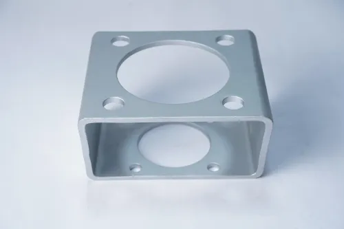
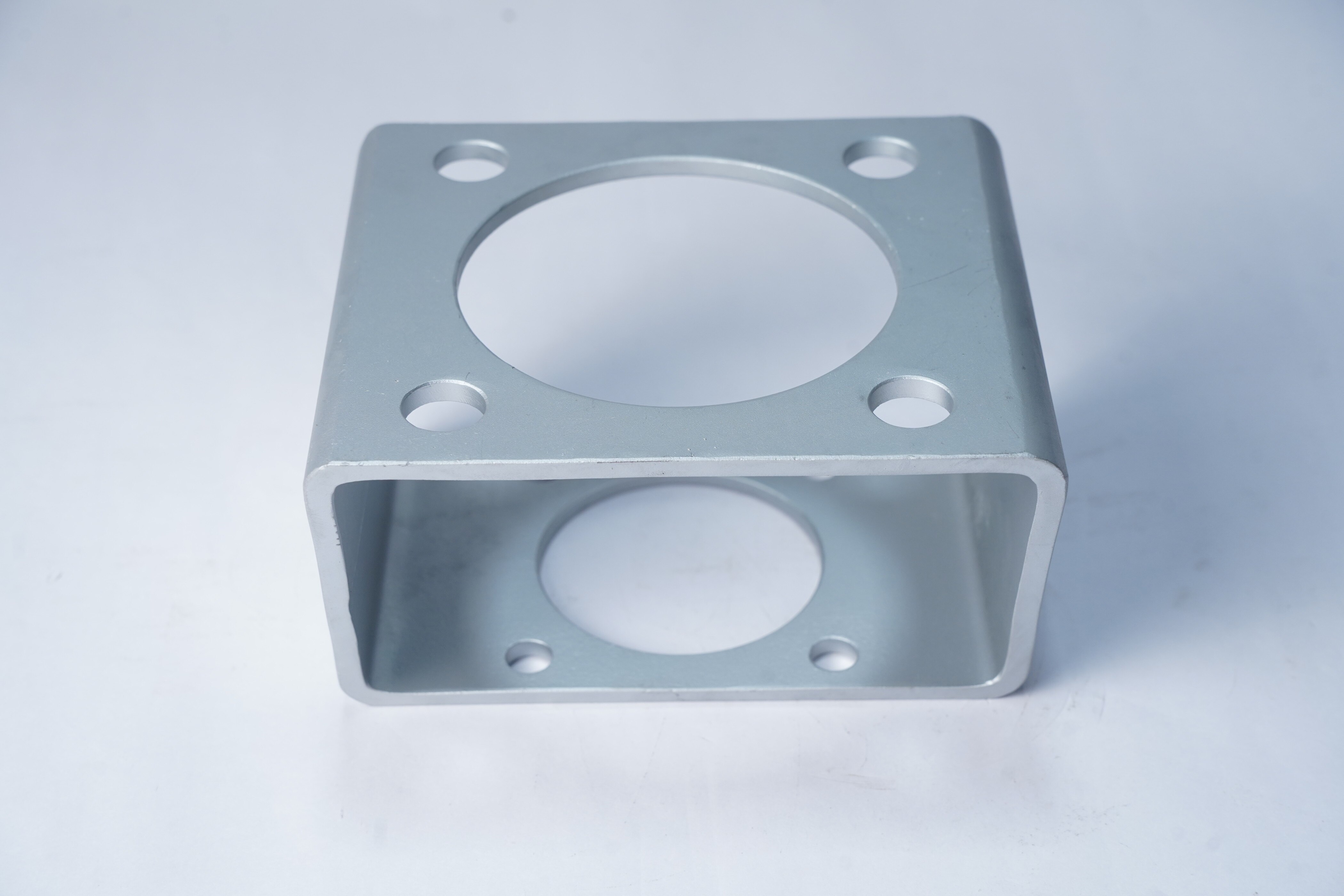
A valve bracket adaptor is the mechanical bridge between the valve body, mounting pad, stem and actuator. It aligns mismatched flanges, holds the actuator at the correct height and transfers torque or thrust through the coupling; a wrong adaptor can bind the stem or bend the mounting hardware.
The main bracket adaptor types for industrial valves are:
| Option | What it does | Suitable assembly |
|---|---|---|
| Direct top-plate adaptor | Joins matching valve and actuator flanges | Quarter-turn ball, butterfly or plug valves |
| Spacer adaptor | Adds height or clearance between flanges | Short stems, insulated pipework or obstructed housings |
| Shaft-extension adaptor | Extends the valve stem to the actuator drive | Deep mounting pads or inaccessible stems |
| Offset or side-mount bracket | Moves the actuator away from the valve centreline | Tight pipework, manual access or unusual orientation |
| Split-clamp or custom transition plate | Connects non-standard shafts or hole patterns | Legacy valves, linear actuators or bespoke interfaces |
For quarter-turn assemblies, start with the valve’s ISO 5211 flange and drive shape, then compare the actuator output drive. ISO 5211 defines attachment-flange and drive-interface dimensions; it does not confirm torque capacity, rotation direction or stem engagement.
Do not confuse a NAMUR pattern with the valve-to-actuator interface. NAMUR commonly mounts positioners and solenoid valves on pneumatic actuators. Confirm actuator orientation, full travel, hard-stop clearance, coupling engagement and manual-override access during a trial assembly. A matching hole pattern alone proves very little.
Match both mounting flanges, not just the ISO code
An adaptor fits only when the valve flange and actuator flange agree in pattern, height and load path. To choose bracket adaptor for valve service, compare the production valve’s mounting pad with the actuator’s actual output flange and drive, not the actuator model name alone.
| Interface check | Compare | Failure if ignored |
|---|---|---|
| Mounting standard | ISO 5211 flange on both sides; do not confuse a NAMUR accessory pattern with the valve interface | A positioner bracket may bolt on while the actuator cannot mount to the valve |
| Flange size | F05, F07, F10 or the stated standard size, including outside dimensions and thickness | Matching codes can still hide different pad geometry |
| Bolt pattern | Hole count, pitch-circle diameter, hole diameter and thread or clearance-hole type | The adaptor aligns in a drawing but cannot be fastened |
| Drive interface | Actuator output square, key, star or female drive against the valve stem shape and size | The motor runs without transmitting torque |
| Centre height and orientation | Distance from each flange face to the drive centreline, plus required actuator position | The coupling sits eccentric or the controls face the wrong direction |
ISO 5211 standardises attachment-flange and drive-interface dimensions; it does not confirm torque, rotation, stem engagement or clearance. A direct ISO 5211 adaptor is shortest and stiffest only when every one of those dimensions matches.
Request interface drawings for both parts and verify the complete assembly with the production valve and actuator. Check coupling engagement, full travel, hard-stop clearance, fastener access, manual override access and binding before approval.
Select the arrangement for the actuator and stem
Choose the actuator arrangement before selecting among industrial valve bracket adaptor options. Quarter-turn ball, butterfly and plug valves use a bracket that preserves rotation direction, actuator orientation and stem engagement. An ISO 5211 flange identifies the mounting interface; it does not confirm torque, rotation, or clearance.
| Arrangement | Suitable adaptor route | Check before approval |
|---|---|---|
| Quarter-turn powered | ISO 5211 bracket with the correct output-drive coupling | Confirm 90° travel, fail position, limit-switch access and pipework clearance |
| Linear powered | Yoke or stem adaptor for globe, diaphragm or pinch valves | Confirm axial thrust, specified travel, stem thread or clamp, and anti-rotation guidance |
| Manual quarter-turn | Bracket or spacer for a hand lever or gearbox | Confirm handwheel or lever access, operating direction and hard-stop alignment |
| Manual linear | Yoke, stem nut or extension arrangement for a handwheel | Confirm stem travel, thrust path and protection from bending loads |
Do not substitute a quarter-turn ISO 5211 bracket for a linear yoke. Also separate NAMUR accessory mounting for a positioner or solenoid valve from the valve-to-actuator interface; the two patterns serve different jobs.
Trial the production valve and actuator together. Check full travel, coupling engagement, hard-stop clearance, manual override access, fastener access and binding. Reject a thin or long unsupported adaptor if actuator reaction torque can flex it, because angular movement causes fretting, loose fasteners and false position feedback.
Measure the drive, clearance and load path
A 2D hole-pattern match can still produce a bracket that binds, flexes or loses drive engagement. Measure the complete load path from actuator output through the coupling and bracket into the valve stem.
| Check | Measure | Failure if missed |
|---|---|---|
| Drive interface | Square, keyed, flat or splined shape; across-flats or key size; depth | Coupling bottoms out, strips or fails to transmit torque |
| Stem engagement | Shaft height, protrusion, diameter and minimum engaged length | The actuator runs while the stem slips or loads unevenly |
| Bracket geometry | Overall height, flange thickness and bolt-hole position | The actuator flange touches the valve or the adaptor twists |
| Operating envelope | Full-turn sweep, hard-stop position and nearby pipework | The assembly reaches a stop before the valve completes travel |
| Fastener path | Bolt length, thread depth, wrench access and edge distance | Fasteners loosen, bottom out or cannot be installed |
Trace torque and reaction forces through the adaptor, not just the actuator weight. A thin plate with a tall spacer creates leverage that can bend the plate or loosen flange bolts; a gusset, shorter stack or stiffer material may be necessary.
Use a production valve and actuator for the trial assembly, then verify:
- Full valve travel and correct rotation direction
- Coupling engagement at both travel limits
- No binding at the hard stops
- Actuator orientation and manual-override access
- Clearance for limit switches, cables and adjacent pipework
Check galvanic compatibility and corrosion exposure before choosing carbon steel or stainless steel. Measure coated drive parts after finishing: a coating can turn a correct fit into an interference fit.
Turn the measurements into a supplier specification
Send the supplier a drawing pack, not a request for “a suitable bracket.” Include the production valve and actuator makes, model numbers, interface drawings, ISO 5211 or other mounting standard, bolt-hole pattern, drive shape and size, shaft height, orientation, rotation direction, torque or axial thrust, travel, material, finish and operating temperature.
- State the valve’s breakaway, running and end-position torque, or the required axial thrust for linear globe, diaphragm or pinch valves.
- Specify the actuator’s output drive, mounting flange, rotation angle, fail position, manual override location and limit-switch orientation.
- Add clearance envelopes for pipework and insulation, hard-stop locations, coupling engagement, fastener access and any anti-rotation feature.
- Define inspection requirements: dimensional report for the flange and drive, material certificate, surface-finish record and drawing revision.
A search for a valve bracket adaptor supplier in Stuttgart does not replace this information. Supplier location is not evidence of compatibility.
Before approval, trial-fit the production valve, adaptor and actuator. Confirm full travel, correct rotation, required fail position, hard-stop clearance, complete stem or coupling engagement, manual override access, accessible fasteners and zero binding through the stroke. Reject a bracket that matches the 2D hole pattern but shifts the load into the coupling or blocks adjacent pipework.
Efficient Precision & System Pvt.Ltd can be assessed on this same drawing pack and trial record, rather than on a catalogue description.
Related product
 | Industrial Valve Efficient Precision and System Pvt. Ltd. is a leading supplier, exporter and manufacturer of Valve Brackets based in India. View product → |
Frequently asked questions
What should you check first when choosing a valve bracket adaptor?
Start with the valve-to-actuator interface, including the valve mounting pad, actuator flange, stem position and coupling arrangement.
Is matching the ISO mounting code enough?
No. Confirm both mounting flanges, bolt-hole pattern, spigot or register diameter, bolt size, orientation and available clearance.
Which measurements determine whether an adaptor will fit?
Measure the stem drive, shaft height, actuator dimensions, surrounding clearance, bolt locations and the torque or thrust carried through the adaptor.
What information should you send to a bracket adaptor supplier?
Provide valve and actuator models, flange dimensions, stem and drive measurements, load data, material requirements, orientation and a dimensioned drawing or photographs.