
A bracket adaptor must do more than connect a valve to an actuator: it must preserve shaft alignment, transmit reaction torque and fit the actual mounting geometry. By the end, you will be able to identify the right interface, compare mounting options, specify materials and tolerances, and request inspection evidence before installation or purchase.
Key takeaways
- Match the adaptor to the valve mounting pad, stem drive and actuator bolt pattern.
- Use direct mounting for compact assemblies; choose brackets when access or alignment needs change.
- Specify material, surface treatment, loads, temperature and corrosion exposure before machining.
- Verify finished parts against drawings, hole patterns, coupling dimensions and inspection records.
What a Bracket Adaptor Does in a Valve Assembly
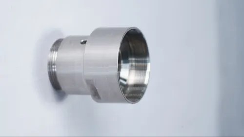
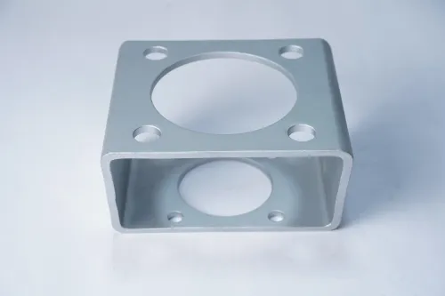
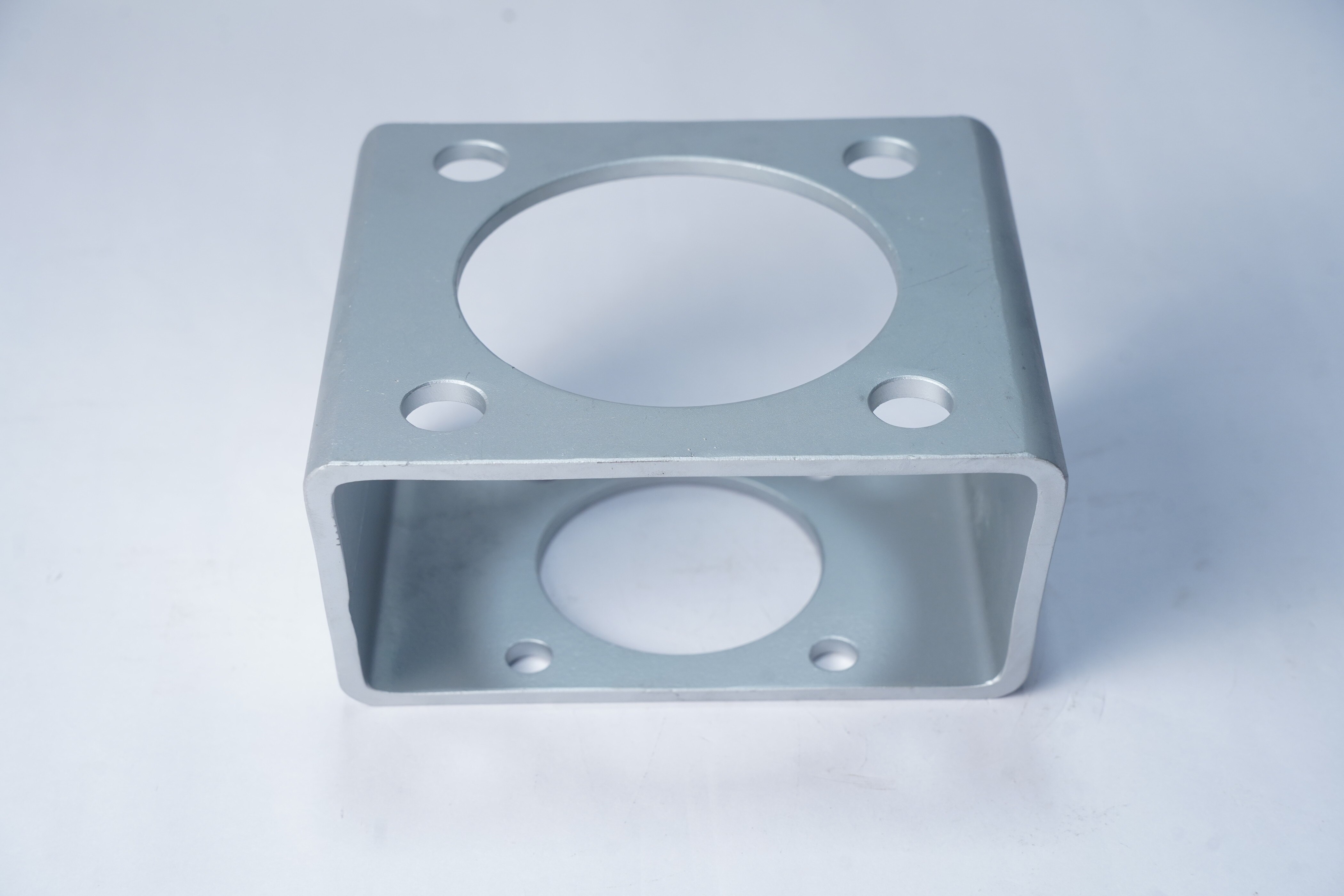
A bracket adaptor forms the mechanical interface between an industrial valve, its actuator and the surrounding support structure. It bolts to the valve body or mounting pad, carries the actuator, and uses a coupling, keyway or square drive to connect the actuator output to the valve stem.
The adaptor must hold the shaft on axis and transmit reaction torque; it is not simply a spacer.
Its practical benefits include:
- Preserving a standard actuator interface while accommodating a valve with a different mounting pattern.
- Distributing actuator and vibration loads into the valve mounting points or a separate pedestal, reducing side loading on the stem.
- Allowing actuator removal without breaking the process-piping connection or disturbing the valve body.
- Providing controlled stand-off for handwheel clearance, tubing, insulation and maintenance access.
The design must withstand the actuator’s output torque and maintain alignment under vibration and temperature changes. Check valve breakaway, running and seating torque against the coupling and adaptor ratings; the bracket adaptor does not create extra actuator capacity. If removal requires dismantling adjacent tubing or recalibrating position feedback, the maintenance benefits shrink.
For projects in Stuttgart, regional sourcing can shorten engineering feedback and replenishment time, but location does not correct an incomplete specification. State the valve model, actuator model, interface dimensions, torque, materials, corrosion protection and inspection requirements.
The adaptor normally sits outside the pressure boundary, yet the complete valve assembly still needs its applicable pressure-equipment conformity assessment.
Match the Adaptor to the Valve Type and Actuator Interface
A quarter-turn butterfly or ball valve commonly uses a bracket adaptor between its ISO 5211 mounting pad and an electric, pneumatic or hydraulic actuator. Linear gate, globe and diaphragm valves need a different arrangement: a bracket supports the actuator above the bonnet, while a stem coupling converts actuator travel into the valve’s required stroke.
| Valve and actuator arrangement | Measurements that prove fit | Failure if missed |
|---|---|---|
| Quarter-turn valve with actuator | ISO 5211 flange size, bolt-circle diameter, hole count and thread; actuator drive-square or key dimensions; shaft diameter, mounting height and coupling depth | The bolts align but the drive bottoms out, leaving the valve partly open |
| Offset valve and actuator | Valve pad height, actuator base height, required stand-off, shaft centreline and available envelope | Side loading bends the stem or prevents full rotation |
| Linear valve with actuator | Stem diameter and thread, stroke length, stem extension, actuator mounting-hole pattern and yoke height | The actuator reaches its limit before the valve seats |
Do not specify only “ISO 5211.” The standard includes multiple flange and drive-size combinations, so record the exact valve and actuator model numbers, rotation angle or stroke, and coupling geometry. Confirm the actuator’s output torque against breakaway, running, seating, differential-pressure, packing-friction, temperature and deposit loads; the adaptor only transfers torque.
For an industrial valve bracket adaptor Stuttgart project, send a dimensioned interface drawing rather than a location-based assumption. Precision valve brackets still need measured hole positions, tolerances and shaft alignment; regional sourcing can shorten feedback, but it cannot correct an incomplete interface definition.
Compare Direct Mounting, Universal Brackets and Precision Designs
Choose direct mounting when valve and actuator share the flange, bolt pattern, shaft drive and adequate support; it has the fewest parts and the lowest alignment risk. Use a fabricated plate for a simple offset or stand-off when loads are modest and you can verify plate thickness, hole positions and weld distortion.
A universal bracket suits repeated projects with varying patterns, but slots and adjustability trade stiffness for flexibility. Select a custom-machined precision bracket when torque, vibration, tight concentricity, limited envelope or maintenance access makes movement unacceptable.
| Option | What it means | When it applies |
|---|---|---|
| Direct mounting | Actuator attaches to the valve’s matching interface | Standardised valve-actuator pair with no offset |
| Fabricated plate | Cut or welded plate adapts hole patterns or height | Low-to-moderate loads and straightforward geometry |
| Universal bracket | Adjustable slots or multiple patterns provide flexibility | Mixed equipment ranges where alignment tolerance is acceptable |
| Custom-machined precision bracket | One-piece or tightly controlled machined interface | High torque, short shaft engagement, vibration or critical alignment |
Do not choose a bracket adaptor manufacturer by the label “precision.” Check maximum machinable envelope, bar diameter, live-tool and cross-drilling capability, heat-treatment and surface-treatment control, inspection equipment, and its ability to hold the shaft-to-mounting-face relationship. A Swiss-type machine suits slender couplings, bushes and drive inserts; larger plates often cost less on a machining centre.
Specify Materials, Load Paths and Service Conditions
Design the load path from the actuator shaft to the valve body, not merely from bolt hole to bolt hole. Check the adaptor, coupling, fasteners and valve flange against actuator output torque, valve breakaway torque, running torque, seating torque, differential pressure, packing friction, temperature and deposits.
The adaptor transfers torque; it does not create extra capacity. Add gussets, generous internal radii and adequate bolt preload where vibration could cause fatigue or fretting.
Material choice must match the external environment and the mating metals. Isolate dissimilar metals with suitable washers or coatings when galvanic corrosion is possible.
| Material | Strength and limitation | Suitable condition |
|---|---|---|
| 1.4404/316L stainless steel | Corrosion resistance; higher cost and thermal expansion than carbon steel | Washdown, humid or chemically exposed installations |
| Coated carbon steel | High stiffness and economical fabrication; coating damage exposes steel | Dry indoor service with defined coating maintenance |
| Aluminium | Low mass; lower stiffness and thread durability | Weight-sensitive assemblies with controlled loads and galvanic isolation |
Specify the actual service temperature at the adaptor, actuator and coupling. Account for thermal expansion, ice, abrasive dust, cleaning chemicals, outdoor UV exposure and hazardous-area restrictions. Keep the bracket outside the pressure boundary unless the complete valve assembly has been assessed through the correct conformity route; a bracket cannot make a non-compliant pressure assembly compliant.
Require precision valve brackets that allow actuator removal without disturbing pipe joints, tubing or feedback calibration. Your drawing should state:
- Valve and actuator models, interface dimensions, stand-off and shaft geometry
- Allowable torque, vibration duty, corrosion protection and fastener grade
- Tool clearance, inspection access and replacement procedure
- Surface finish, temperature limits and material certificates
Buy and Verify a Valve Bracket Supplier’s Finished Part
A finished part is acceptable only when its dimensions, materials and records match the purchase order. Treat “valve bracket supplier germany” as a location search, not proof of capability; a nearby source still needs to hold the shaft-to-mounting-face relationship.
1. Request the controlled drawing, valve and actuator models, ISO 5211 flange and drive sizes, coupling geometry, stand-off, torque rating, fastener specification, material grade, surface-treatment or passivation specification, and the required EN 10204 material certificate.
2. Check the bracket adaptor manufacturer’s capability before approval: maximum machinable envelope, bar diameter, live-tool and cross-drilling capacity, heat-treatment and coating control, and inspection equipment. Efficient Precision & System Pvt.Ltd should be assessed by these capabilities, not by a supplier label.
3. Require inspection records for the bolt circle, mounting height, shaft or coupling fit, hole locations, critical thicknesses and shaft-to-mounting-face relationship. Compare the recorded values with drawing tolerances, not with a general “passed” statement.
4. Inspect the delivered part for burrs, damaged threads, coating voids, incorrect fasteners, corrosion and interference with the valve or actuator. Confirm that the coupling transmits the actuator’s maximum output torque; the adaptor does not add torque capacity.
5. Verify the complete assembly’s conformity route separately. The adaptor normally sits outside the pressure boundary, and ISO 9001 certification alone does not prove part acceptance. A search for “industrial valve bracket adaptor stuttgart” may find faster engineering feedback, but proximity cannot repair an incomplete interface definition.
Related product
 | Industrial Valve Efficient Precision and System Pvt. Ltd. is a leading supplier, exporter and manufacturer of Valve Brackets based in India. View product → |
Frequently asked questions
What does a bracket adaptor do in an industrial valve assembly?
It connects the valve, actuator and support structure while transmitting actuator torque to the valve stem through a coupling, keyway or square drive.
How do you match a bracket adaptor to a valve and actuator?
Check the valve type, mounting pad, stem interface, actuator bolt pattern, output dimensions, available clearance and required torque before selecting the adaptor.
How do direct mounting, universal brackets and precision adaptors compare?
Direct mounting reduces parts and assembly space, universal brackets offer flexibility, and precision adaptors improve alignment and repeatability when interfaces must fit closely.
What should you verify when buying a finished valve bracket adaptor?
Compare the part with the approved drawing, checking material, hole locations, coupling dimensions, surface finish, deburring, identification and inspection records.