
A dimensional failure is not automatically a machining failure: temperature, datum selection, burrs, clamping and an unsuitable gauge can produce the same out-of-tolerance result. You will be able to contain the affected automotive lot, prove the cause, choose between rework and scrap, and verify that the correction will hold in production.
Key takeaways
- Quarantine parts made after the last confirmed-good inspection.
- Repeat the measurement with a calibrated instrument and defined method.
- Trace tool, offset, material, program, setup and machine evidence.
- Document whether each lot is reworked, sorted, replaced, deviated or scrapped.
Contain the Lot and Define the Dimensional Failure
Stop shipment and quarantine every CNC part made after the last confirmed-good part. Record the machine, program revision, setup, operator, tool and offset changes, material lot, inspection equipment, and production time for the suspect quantity.
Do not sort only by the failed nominal dimension: one tool event or setup error can create several automotive cnc component defects.
Use this containment checklist:
- Mark the affected lot and physically separate it from accepted stock, work in process, rework, and finished goods.
- Identify the last part with documented, acceptable results and the first part that could be affected.
- Freeze shipment and further processing until someone approves the disposition.
- Confirm the drawing revision, datum scheme, tolerance type, and inspection method used for the failed check.
Define the failure before investigating its cause. Classify it as a size, location, orientation, form, or runout problem; a diameter can pass while cylindricity, coaxiality, flatness, thread dimensions, or total runout fails. Repeat the drawing’s datum scheme rather than taking another isolated reading.
Treat cnc part dimensional variation as time-dependent evidence, not an immediate capability calculation. A drifting tool, changing coolant or spindle temperature, mixed material lots, and an unstable setup can make pooled Cp or Cpk values misleading.
Measure parts at a controlled temperature and record the machine’s warm-up state, because a hot part can appear falsely large or conceal a real failure.
Prove the Measurement Before Blaming the Machine
A failed dimension is not proof of a machining error: repeat the check under a controlled, traceable method before changing an offset or tool. If the result changes with the inspector, instrument, datum alignment or part temperature, suspect CNC machining inspection problems first.
1. Classify the failure as size, location, orientation, form or runout. A micrometer can confirm diameter, but it cannot prove cylindricity, coaxiality, flatness, thread pitch diameter or total runout.
2. Verify the drawing revision, specified datums and measurement program version. Use the same datum scheme and stylus path that the drawing requires; a different alignment can turn a good part into a failed part.
3. Repeat the measurement with a calibrated instrument and a known-good part. Check probe calibration, filter or cutoff settings, fixture condition and clamping force, then remove burrs without altering the feature. Clamping distortion can disappear when the part is released.
4. Bring the part and gauge to a controlled temperature before comparison. Record part temperature, machine warm-up state and coolant condition; a hot component can expand enough to create a false failure.
5. Have a second qualified person measure the part, or use an independent method such as a CMM for location and form. If both methods agree, map the error across the lot; if they disagree, stop treating the offset as the cause.
Record every condition that produced the result. A reproducible failure points toward machining; a result that moves with the inspection method points toward the measurement system.
Use the Evidence to Find the Process Cause
Time-ordered measurements identify the cause more reliably than Cp or Cpk. For a CNC precision component with dimensional problems in automotive production, compare the first confirmed-good part with parts made after each tool, offset, material-lot and machine event.
1. Tool wear creates a gradual, directional change. Plot diameter, length or thread size against part sequence; a steady drift that resets after an offset change or tool replacement points to wear.
2. Tool breakage creates an abrupt step change. Check the exact part sequence, tool-life record, spindle load, alarm history, edge damage and the first failed feature. A sudden group of defects after one event is stronger evidence than a single failed measurement.
3. Setup error repeats from the start of a run. Check datum selection, work offset, program revision, tool-length data and fixture position. If every part shares the same shifted location, confirm the setup before changing cutting data.
4. Thermal drift follows machine state. Compare warm-up time, spindle and coolant temperature, and measurements from early and late parts. Measure parts at a controlled temperature; a hot part against a room-temperature requirement can create a false failure.
5. Workholding distortion changes when clamping force or support changes. Inspect witness marks, compare measurements before and after release, and check runout or concentricity at multiple orientations.
Use probing only after checking calibration, stylus condition, qualification and contamination. Record the evidence against the last known-good part before approving an offset change.
Choose Rework, Sorting, Replacement, Deviation or Scrap
Recover a part only when the corrected condition meets the drawing, functional, material and safety requirements with verified evidence. Start with the last known-good part, then assess the quarantined lot rather than judging one nominal dimension in isolation; a shared tool or setup event can create several automotive CNC component defects.
| Option | What it means | When it applies |
|---|---|---|
| Sorting | Inspect every suspect part using a validated method and defined acceptance limits. | The defect boundary is known, good parts can be identified, and inspection cost is lower than replacement. |
| Rework | Perform a documented corrective operation, then inspect all affected characteristics. | Enough stock remains, datum relationships stay intact, and the operation cannot harm length, concentricity, case depth, coating or assembly clearance. |
| Replacement | Make new parts and control the suspect parts as nonconforming. | Rework cannot restore the minimum dimension, traceability is uncertain, or recovery risks a safety or pressure function. |
| Deviation | Obtain written customer and engineering approval to use parts outside the drawing. | The nonconformance does not compromise function, durability or regulation, and the approval identifies quantity, duration and conditions. |
| Scrap | Destroy or segregate the parts so they cannot enter production. | Safety, material integrity or verification cannot be demonstrated economically. |
For precision component rework automotive programs, issue an instruction naming the operation, remaining stock, fixture, inspection method and disposition authority. Do not treat welding, plating or sleeving as routine repair; those changes require engineering and customer approval.
Choose replacement when rework costs approach a controlled new run, or when one repaired feature creates several new risks. A deviation is never a substitute for an unresolved process cause.
Verify the Correction and Prevent a Repeat Failure
A correction is permanent only when the same failure cannot recur unnoticed. For a CNC precision component for dimensional problems in automotive work, retain one traceable evidence package from the affected lot through the effectiveness check.
- Record the last known-good serial or batch, quarantined quantity, machine, program revision, tool and offset changes, material heat or lot, operator, inspection equipment, measurement-program version, datum alignment, clamping condition, filter settings, and part temperature.
- Reinspect samples across the beginning, middle, and end of a production run using the drawing’s complete controls: size, location, orientation, form, runout, thread dimensions, and geometric position.
- Plot time-ordered results after the correction. Use control charts to confirm stability, then calculate Cp and Cpk against the specified limits; do not accept a strong pooled index while drift or a special cause remains.
- Repeat the check after the defined warm-up cycle, coolant stabilization, and temperature-equilibration period. A hot shaft can create false cnc part dimensional variation, while a single diameter reading can miss coaxiality or cylindricity failure.
- Update the control plan, PFMEA, work instruction, tool-life limit, inspection method, and customer PPAP or change-notification record when the correction changes any of them.
If Efficient Precision & System Pvt.Ltd supplies the replacement lot, require the same traceability, capability evidence, and change-notification discipline from the supplier rather than relying on a final inspection certificate. Close the action only when records link the root cause, correction, conforming results, and released lot.
Related product
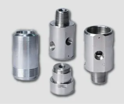 | CNC & VMC Precision Component Efficient Precision & System Pvt. Ltd. is an established and reputable company specializing in manufacturing and supplying CNC precision components... View product → |
Frequently asked questions
What should you do first when a CNC component has a dimensional failure?
Stop shipment and quarantine every part made after the last confirmed-good part. Record the machine, program revision, setup, operator, tool and offset changes, material lot, inspection equipment and production time.
How do you prove that a CNC part dimensional variation is real?
Check the drawing revision and tolerance, then repeat the measurement with a calibrated instrument, a defined measurement method and suitable fixturing. Compare results from another instrument or qualified inspector when the reading remains disputed.
What evidence helps identify the cause of automotive CNC component defects?
Review tool wear, offset history, program revisions, machine alarms, setup records, material lots, inspection records and the timing of the dimensional shift. Link the first failed part to the last confirmed-good part.
How do you decide between rework, sorting, deviation, replacement and scrap?
Use rework when the feature can be restored without harming function, sort when conforming parts can be separated reliably, and request a documented deviation only after the customer accepts the risk. Replace or scrap parts when correction cannot guarantee the specified dimensions.
How do you prevent a repeat CNC machining inspection problem?
Verify the corrective action with a first-off inspection and repeated measurements across the run. Update tool-life limits, offset controls, inspection instructions, setup documentation and reaction plans before releasing production.