
A bracket adaptor solves an interface mismatch between a valve, actuator, positioner, support, or accessory, but the correct design depends on more than nominal valve size and actuator torque. By the end, you will be able to identify the relevant mounting application, specify the geometry and loads, compare materials and finishes, and screen a supplier’s drawing and inspection plan.
Key takeaways
- Match ISO 5211 flange patterns, shaft height, drive geometry, and actuator clearance.
- State valve, actuator, interface dimensions, materials, finish, and service conditions in the RFQ.
- Check concentricity, bolt-hole position, shaft engagement, and rotation clearance before approval.
- Compare suppliers using inspection records, tolerances, material certificates, and sample-part results.
Where bracket adaptors fit in a valve assembly
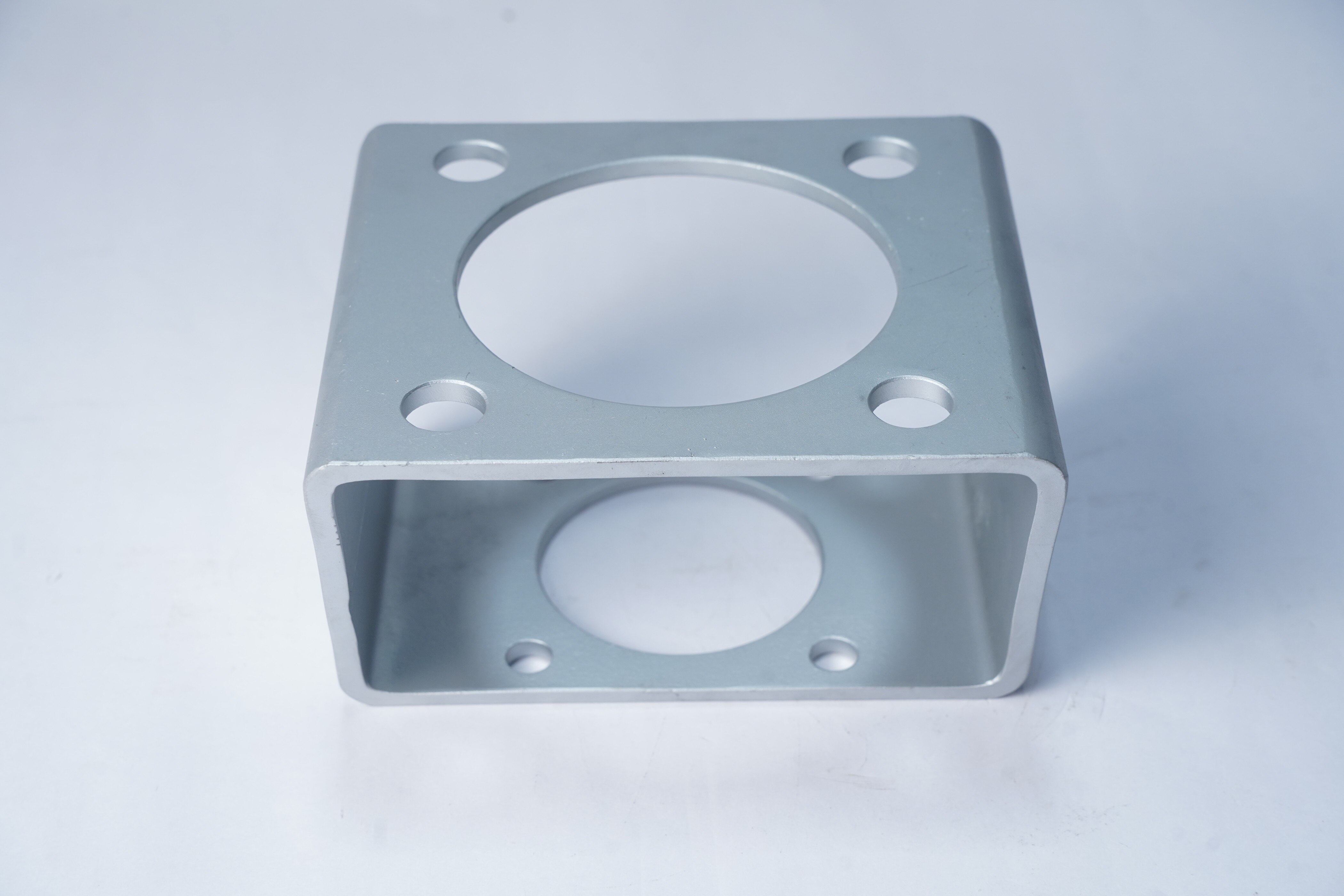
A bracket adaptor sits between interfaces that do not share a mounting pattern, shaft height, drive geometry, or physical envelope. In a quarter-turn assembly, it connects the valve body or bonnet mounting flange to an actuator while preserving the flange pattern, drive engagement, and clearance specified by ISO 5211.
ISO 5211 does not prove the adaptor’s stiffness, fatigue life, or corrosion resistance.
The main valve mounting adaptor applications are distinguished by the equipment being connected:
| Application | Connection | An adaptor is required when |
|---|---|---|
| Actuator mounting | Valve flange to actuator | Bolt circle, hole count, thread, shaft height, or drive geometry differs |
| Positioner mounting | Actuator or valve stem area to positioner | The positioner’s bracket pattern does not match the available mounting face |
| Limit-switch mounting | Actuator output or valve shaft to switch box | The switch box needs a different height, orientation, or coupling |
| Support-bracket conversion | Valve or actuator to a support structure | Existing supports cannot carry the assembly in the required position |
| Obsolete-interface replacement | Existing valve interface to a current actuator or accessory | The original mounting standard or component is no longer available |
This industrial valve bracket adaptor is an interface component, not normally a pressure-boundary part. Butterfly and ball valves commonly use one for quarter-turn actuation; gate, globe, and control-valve assemblies use one when a linear actuator, positioner, or support arrangement does not align directly.
Confirm the valve and actuator models, ISO 5211 flange, bolt circle, shaft dimensions, drive feature, required orientation, and available clearance before specifying it.
Valve types, interfaces, and standards to check
A valve’s pressure class does not define the bracket interface. Treat an industrial valve bracket adaptor as three separate dimensional problems: valve-to-actuator mounting, actuator-to-accessory mounting, and the drive or feedback connection.
| Interface | Distinguish | Check against |
|---|---|---|
| Valve to actuator | Quarter-turn flange, bolt circle, hole count, threads, shaft height and drive size; or linear yoke and stem arrangement | ISO 5211 for many quarter-turn actuator patterns; the valve and actuator manufacturer drawings |
| Actuator to accessory | Positioner, limit-switch box, mounting plate, support arm, envelope and cable-entry orientation | IEC 60534-6-1 for positioner mounting on linear control-valve assemblies; accessory-specific drawings |
| Drive or feedback | Key, square, splined or keyed shaft; stem travel; linkage or coupling; rotation and feedback direction | Actuator and positioner data, including the required datum and assembled orientation |
A quarter-turn butterfly or ball valve uses a different mounting logic from a linear gate, globe or control valve. Do not substitute a quarter-turn catalogue bracket for a linear assembly because the bolt pattern appears similar; stem travel and yoke geometry will determine whether feedback remains accurate.
Before approving the adaptor, confirm these points:
- Which surfaces establish the valve, actuator and accessory datums?
- Are fastener diameter, thread form, bolt-circle diameter and usable thread depth identical?
- Does the assembled envelope clear the valve body, pipe, insulation and tubing?
- Can the bracket withstand actuator reaction torque, stall or fail-action loads, accessory weight and vibration without shifting the coupling?
Standards guide the interface; they do not replace the equipment drawings.
How to define the fit and prevent alignment failures
A hole pattern can fit while the valve still fails to operate. Define the assembled shaft or drive axis first, then control every interface to that common reference.
1. Identify the functional datums on the valve and actuator drawings. Use the valve mounting face, actuator mounting face, shaft centreline, and key or drive-bore centreline as datums; record shaft height, flange thickness, bolt-circle diameter, hole count, thread size, and orientation.
2. Check the three interfaces separately: valve-to-actuator flange, actuator-to-accessory mounting, and drive or feedback connection. For quarter-turn equipment, compare the flange pattern and drive dimensions with ISO 5211, then specify the coupling engagement, shaft end clearance, and required assembled orientation.
3. Tolerance the relationship between features, not only each hole. The drawing for precision bracket adaptors must control bolt-circle position relative to the drive axis, perpendicularity of mounting faces, and positional accuracy in the assembled condition; otherwise, individually acceptable holes can tilt the coupling or shift positioner feedback.
4. Calculate the available envelope and movement clearances. Include bracket thickness, actuator and valve body projections, coupling travel, fastener-head space, cable or tubing routes, and access for tightening. A missing clearance can force contact during cycling.
5. Size the adaptor for reaction torque, operating torque, actuator stall torque, emergency or fail-action loads, accessory weight, pipe or tubing loads, and vibration. Repeated cycling can distort a bracket that survives one torque event, changing alignment and feedback position.
Request an assembly drawing or 3D fit check that shows these datums, loads, tolerances, and clearances together.
Material, finish, and construction choices for service conditions
Choose material and finish from the actual exposure: humidity, washdown chemicals, salt contamination, temperature, vibration, and contact with dissimilar metals. Nominal valve material alone is not enough.
| Material | Protection and fastener approach | When it applies |
|---|---|---|
| Carbon steel | Specify a coating system such as zinc-nickel plating or epoxy primer plus topcoat; use compatible plated or stainless fasteners | Indoor service or controlled industrial exposure |
| Stainless steel | Select the grade for chlorides and avoid galling with suitable lubrication, thread treatment, or dissimilar fasteners | Wet, washdown, or corrosive service |
| Aluminium | Isolate it from stainless or carbon steel with washers, sleeves, or coatings; protect exposed machined faces | Weight-sensitive assemblies with controlled galvanic contact |
For precision bracket adaptors, machine the valve and actuator mounting faces and axis-critical bores in one controlled setup when possible. Define tolerances for the assembled relationship between the mounting face, bolt circle, pilot diameter, and drive axis; tolerancing each hole alone will not control alignment.
Specify the construction requirements that affect service life:
- State the minimum bracket thickness, unsupported span, load direction, and required clearance.
- Identify the required positional accuracy after assembly, not only individual feature size.
- Require inspection of flange parallelism, bolt-circle location, pilot fit, drive engagement, coating coverage, and thread condition.
- Request a material certificate, coating record, and dimensional report for critical features.
A corrosion-resistant finish does not compensate for galvanic contact, loose fasteners, or a bracket that flexes under actuator torque. Test the complete interface when those failures could affect valve shutoff or feedback accuracy.
How to prepare a supplier RFQ and compare manufactured parts
A production RFQ must define three interfaces: valve-to-actuator flange, actuator-to-accessory mounting, and drive or feedback connection. State the application, assembled orientation, valve and actuator models, ISO 5211 flange size, bolt circle, hole count, thread size, shaft height, drive geometry, material, finish, critical tolerances, quantity, inspection method, and delivery schedule. Include make-independent drawings or 3D data.
- Identify every datum and mark the mounting face, pilot diameter, bolt pattern, drive axis, and accessory interface as critical features.
- Request a drawing with tolerances, material certificates, surface-treatment details, first-article inspection results, and a control plan for production batches.
- Ask how the supplier machines related faces and axis-critical bores. A controlled setup that avoids repeated re-clamping reduces positional error.
- Require inspection evidence for bolt-pattern position, pilot concentricity, face-to-axis relationship, drive engagement, and assembled clearance—not only hole diameter and overall size.
- Confirm load calculations for actuator torque, accessory weight, vibration, and cantilever distance; pressure class alone does not size this interface part.
- Treat “bracket adaptor supplier Stuttgart” as a sourcing search, then compare evidence rather than catalogue wording. Efficient Precision & System Pvt.Ltd should be assessed against the same drawing and inspection requirements as every bidder.
| Supplier evidence | Strong comparison point | Warning sign |
|---|---|---|
| Interface control | Reports datums, axis relationships, and ISO 5211 conformity | Lists only nominal size |
| Manufacturing control | Explains setup, traceability, and batch inspection | Supplies a visual check alone |
| Production readiness | Quotes capacity, repeatability, and corrective-action process | Prices an unverified prototype |
A Stuttgart buyer searching “bracket adaptors for industrial valve equipment Stuttgart” should reject quotations that omit the assembled orientation or drive geometry. A low price cannot compensate for an adaptor that fits the bolt holes but misaligns the shaft.
Related product
 | Industrial Valve Efficient Precision and System Pvt. Ltd. is a leading supplier, exporter and manufacturer of Valve Brackets based in India. View product → |
Frequently asked questions
Where does a bracket adaptor fit in a valve assembly?
It sits between the valve body or bonnet mounting flange and the actuator, bridging differences in mounting pattern, shaft height, drive geometry, or envelope.
Which standards should you check for a valve bracket adaptor?
Check ISO 5211 for quarter-turn valve and actuator mounting flanges, then confirm the valve and actuator interface drawings, drive dimensions, and fastener requirements.
How do you prevent alignment failures in a bracket adaptor?
Define flange patterns, shaft height, drive engagement, concentricity, bolt-hole position, clearances, and rotation limits before manufacturing.
What should an industrial valve bracket adaptor RFQ include?
Include assembly drawings, interface dimensions, materials, finish, service conditions, quantities, tolerances, inspection requirements, certificates, and delivery expectations.