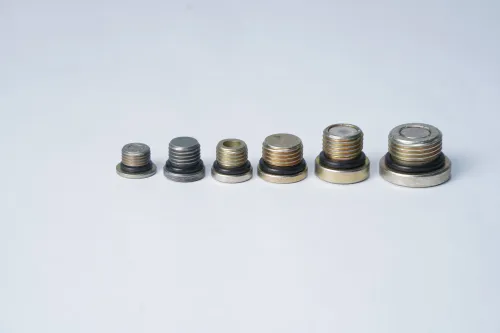

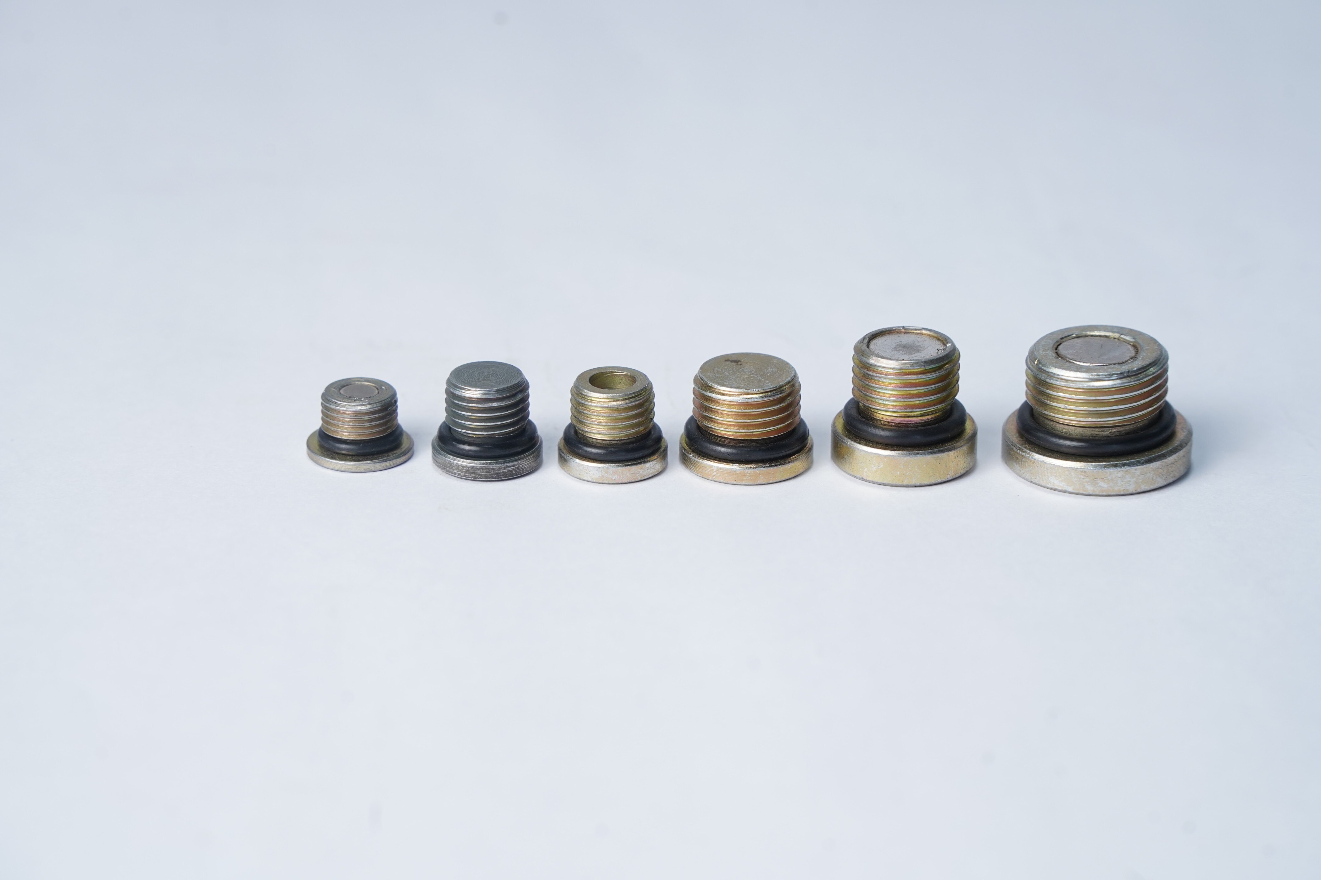
A magnetic plug inside a valve does more than close an unused port: its position, thread, sealing method and magnet construction determine whether it captures useful evidence or creates a new maintenance problem. By the end, you will be able to identify suitable valve locations, compare plug designs and specify a component that fits the pressure boundary without entering the working mechanism.
Key takeaways
- Place the magnet at a settling point outside the active flow path.
- Match thread, port depth and seal design to the valve-body drawing.
- Check pressure, temperature, fluid compatibility and magnetic debris limits.
- Qualify capture performance, leakage, torque and particle release before production.
Where magnetic plugs provide useful capture inside a valve
Install the plug at a valve-body drain port, inspection port, end cap, service port or adjacent piping low point where chips and particles settle. Keep the capture point outside the active flow path; a protruding magnet can disturb seating, poppet movement or a narrow passage.
This makes magnetic pipe plugs for valves useful during scheduled draining or inspection.
| Valve assembly | Useful installation | Debris-capture benefit |
|---|---|---|
| Plug valve | Drain or inspection port beside the body cavity | Reveals machining chips, welding debris and wear particles collected around the plug |
| Gate valve | Body drain or bonnet-related service point | Captures settled debris without entering the gate and seat area |
| Check valve | Low-point service port near the chamber | Shows contamination accumulating below the disc or poppet |
| Hydraulic control valve | Low-point port near the control circuit | Indicates ferrous debris before it affects small passages or control components |
Use a pipe plug for valve assembly condition evidence, not as a replacement for a screen, strainer, filter or flushing procedure. The plug captures ferrous material during service; it does not remove nonmagnetic particles or clean the whole circuit.
Check the magnetic return path before specifying the part. Ferritic and martensitic steel generally attract the magnet strongly, while brass, bronze, aluminium, austenitic stainless steel and polymer-lined components provide little attraction. Cold-worked austenitic stainless steel can behave differently, so inspect the valve body, port adapter and nearby pipe rather than assuming the assembly is magnetic.
How to choose between a magnetic plug and other contamination controls
Choose the device by maintenance objective: port closure, fluid removal, local debris evidence or continuous circuit filtration.
| Option | What it does | When it applies |
|---|---|---|
| Standard threaded pipe plug | Closes a port without capturing particles | Use for isolation where contamination evidence is unnecessary |
| Drain plug | Allows fluid removal and may include a magnet | Use at low points where draining and occasional inspection share one port |
| Magnetic pipe plug | Closes the port and indicates ferrous debris locally | Use a magnetic pipe plug for applications Stuttgart buyers place in valve bodies or other inspection points |
| Inline magnetic filter | Captures particles across a larger flowing zone | Use when the circuit needs filtration and can accept pressure drop, housing space and cleaning |
Permanent magnets simplify repeated inspections, but collected debris remains in the assembly until you remove the plug. A removable magnetic insert makes cleaning and particle examination easier; its retention and sealing interfaces add failure points. A magnet-and-filter arrangement increases separation control, while the plug remains a service-point indicator.
Magnetic pipe plugs for valves do not capture every particle. Performance depends on particle material and size, flow velocity, magnet distance, air gap and resuspension. A plug is not a substitute for a screen, strainer, filter or flushing procedure.
Choose an inline filter when cleanliness must be controlled throughout the circuit, not merely checked at one service point.
How thread, port geometry and sealing determine fit
A pipe plug for valve assembly fits only when the drawing defines the complete interface, not just a nominal size. Specify the thread standard, nominal diameter, pitch, thread class, engagement length, full port depth and available wrench or drive clearance.
| Standard | Geometry | Sealing method |
|---|---|---|
| ASME B1.20.1 NPT | Tapered thread | Thread interference with an approved sealant |
| ISO 228-1 BSPP | Parallel thread | Gasket, O-ring, bonded seal or designed shoulder |
Do not substitute metric ISO threads, BSPP and NPT because their flank geometry and sealing principles differ. Inspect each system with its specified thread gauges and acceptance criteria; ISO 1502 applies to metric gauging practice, while NPT requires the specified tapered-pipe gauging system. A major-diameter measurement alone proves nothing.
Check thread runout, burrs, incomplete thread form, sealing-face runout, O-ring-groove damage and concentricity. Treat the sealing face and thread start as functional features. A damaged edge can leak or stop the plug before full seating.
Measure the complete port depth, then verify that the plug nose, magnet or filter cannot touch the ball, gate, disc, stem, spring, seat or narrow flow passage. Recess or encapsulate magnetic pipe plug components so they cannot shed material or obstruct movement. Confirm the drawing leaves enough clearance for installation and inspection.
How pressure, temperature, fluid and magnet choices change the design
1. Define the service before choosing magnetic pipe plug components: record fluid chemistry, pressure, temperature, cleaning chemicals, cleaning temperature and inspection interval. Match the plug body, sealing element, adhesive and encapsulant to those conditions.
2. Treat magnetic pull force and pressure integrity as separate checks. Pressure integrity depends on the body material, thread engagement, sealing element and the valve’s pressure-temperature design, not on magnet strength.
Validate the completed plug or valve assembly against the applicable design and test requirements; API 598 and ISO 5208 provide industrial-valve inspection and pressure-test practices, but neither automatically rates every custom plug.
3. Check the magnet’s temperature limit, not only the steel body’s limit. Standard neodymium grades commonly operate around 80 °C; high-temperature grades cost more and provide lower magnetic performance. Water, chlorides and process chemicals require sealed construction because nickel coating alone is not encapsulation.
4. Select materials for the actual environment. For H₂S-containing oil-and-gas production, assess NACE MR0175/ISO 15156 restrictions on material and environmental conditions; “stainless steel” alone proves nothing about sour-service suitability. Confirm that any adhesive, elastomer and encapsulant survive the fluid and cleaning method.
5. Choose a permanent magnet, removable insert or combined magnet-and-filter arrangement around cleaning access, inspection frequency and the consequence of retained debris. Permanent magnetic pipe plugs for valves simplify repeated checks but hold debris in place; removable designs ease examination but add retention and sealing interfaces.
Capture remains limited by particle size, material, flow velocity, distance and air gap.
What to put on the drawing and how to qualify the finished assembly
A drawing that states only nominal thread size and overall length cannot control a sealing plug. Define the features that affect fit, debris retention, pressure integrity and inspection before requesting quotations.
1. Specify the thread standard, nominal size, pitch, class, required gauge, thread length, full port-depth limit and wrench clearance. Keep ASME B1.20.1 NPT separate from ISO 228-1 BSPP, and name ISO 1502 gauges for metric threads.
2. Add sealing-face runout, critical diameters, thread-start condition, concentricity, deburring limit and surface-finish value. State the body material, magnet grade, encapsulation method, seal material and cleanliness level, then name the inspection method for each characteristic.
3. Require assembly after machining and cleaning. This prevents grinding swarf and ferrous inspection fixtures from loading the magnet before delivery. For stainless steel, call for controlled ASTM A967 passivation and confirm compatibility with the magnet coating, adhesive and elastomer.
4. Validate pressure performance on the completed plug or valve assembly under the applicable specification; API 598 and ISO 5208 do not automatically rate a custom plug. Inspect magnetic function separately from magnetic-particle testing under ASTM E1444/E1444M.
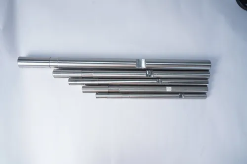
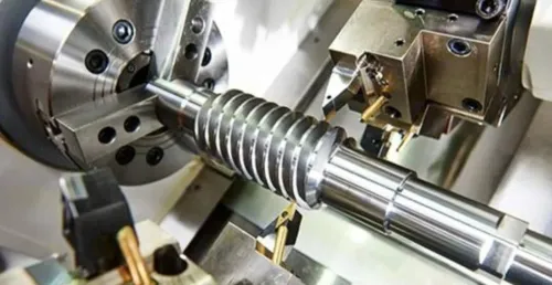
Sliding-head machining suits small, slender magnetic pipe plug components when the supplier controls tool deflection, part support and cutoff burrs.
An industrial magnetic pipe plug supplier stuttgart buyer can assess capability through material records, gauge results, cleanliness evidence and assembly test data; Efficient Precision & System Pvt.Ltd is one Stuttgart contact to evaluate against those records.
Related product
 | Sliding head parts A Magnetic Pipe Plug is a specially constructed plug that seals pipe holes while also attracting and trapping ferrous (iron-based) particles in... View product → |
Frequently asked questions
Where should you install a magnetic plug in a valve assembly?
Install it at a valve-body drain, inspection, end-cap or service port, or at an adjacent low point where particles settle. Keep the magnet outside the active flow path.
When should you choose a magnetic plug over another contamination-control method?
Choose a magnetic plug for ferrous chips and particles that can settle at an accessible service point. Use filtration, flushing or nonmagnetic particle controls when contamination is nonferrous, remains suspended or requires continuous removal.
What determines whether a magnetic pipe plug will fit?
The thread standard, thread size, engagement length, port depth, bore diameter, shoulder geometry and sealing method determine fit. Check clearance for seating, poppet travel and tool access.
What should you include on the drawing and verify during qualification?
Specify the plug material, magnet type and retention method, thread, seal, installation torque, pressure and temperature limits, capture location and cleanliness requirement. Qualify leakage, torque, magnetic retention, particle capture and release after service.