
The better shaft is the one that survives the valve’s combined torque, bending, pressure, temperature, sealing and cycling demands within the available envelope. By comparing section geometry, valve type, interfaces, materials and inspection needs, you can choose a solid or hollow design without relying on weight or nominal strength alone.
Key takeaways
- Choose a solid valve shaft when the outside diameter already meets torque and fatigue requirements.
- Use a hollow shaft only when weight, inertia or material efficiency justifies its added design controls.
- Size diameter, wall thickness and unsupported span as one bending and fatigue system.
- Verify seals, pressure boundaries, bore closures and machining tolerances before approving the shaft design.
What the shaft cross-section really changes
A solid valve shaft outperforms a hollow shaft when the available outside diameter already gives enough torque capacity, bending stiffness and fatigue margin. In solid shaft vs hollow shaft for industrial valves, the solid option is usually the lower-risk choice because it avoids bore closures, thin walls and internal leakage paths.
For a circular shaft, torsional resistance follows the polar second moment of area, J. A solid shaft has J = πd⁴/32; a hollow shaft has J = π(Do⁴ − Di⁴)/32. At the same outside diameter, the solid section is stiffer and stronger.
At the same mass, the hollow section uses material more efficiently because its outer wall sits farther from the axis.
| Option | Structural effect | When it applies |
|---|---|---|
| Solid shaft | Highest strength and stiffness at a fixed outside diameter; simpler sealing and retention | Use when the envelope already meets torque, bending and fatigue requirements |
| Hollow shaft | Lower mass or greater J for the same mass, but with wall and closure demands | Use when actuator inertia, unsupported span or diameter limits justify the added complexity |
Do not judge the hollow design from its tube alone. Keyways, drive flats, cross-drilled holes, threads, grooves and abrupt solid-to-hollow transitions can dominate fatigue life. A thin wall, poor blending or a pressure-connected bore can erase the theoretical advantage through stress concentration, leakage, cleaning and closure requirements.
Match the shaft to the valve and operating load
Torque alone can mislead the industrial valve shaft comparison. Select the section for torque plus bending, axial load, bearing reaction and unsupported span; a longer span raises deflection and fatigue risk even when torsional strength looks adequate.
| Valve type | Loads that drive selection | Shaft choice |
|---|---|---|
| Butterfly | Disc bending, seating torque, flow torque and bearing reactions | A hollow valve shaft works when its outside diameter, wall and fatigue margin handle the combined load; solid is safer when diameter cannot increase |
| Ball | Torque, pressure-induced thrust and stem-ejection load | Use solid or hollow only after checking the shoulder, collar, retention and ball interface |
| Gate | High seating and unseating torque, axial thrust and longer stem span | Solid often suits high-load, low-cycle service; hollow suits a larger diameter within a mass limit |
| Check | Disc impact, hinge-pin bending and flow vibration; no continuous actuator torque | Prioritise stiffness, wear and fatigue at the hinge; a hollow pin fits only with adequate wall and span control |
Pressure class increases pressure-boundary and retention demands, while high temperature changes clearance, seal friction and material strength. Frequent cycling makes torsional stiffness, surface finish and fatigue life more important than static strength.
- Match the actuator type and coupling to the shaft: ISO 5211 mounting does not guarantee adequate key, square, anti-rotation or engagement capacity.
- For short, low-cycle stems, a solid shaft is the lower-risk choice when its diameter already meets the load.
- For long or high-cycle stems, increase outside diameter before removing material; verify seal contact and deflection.
- Recheck the design at minimum and maximum temperature, pressure class and actuator torque.
Size the diameter, wall and unsupported span together
Calculate the section from the loads and the interfaces, not from a preferred construction. For a solid valve shaft, use J = πd⁴/32 for torsion and Z = πd³/32 for bending. For a hollow valve shaft, use J = π(Do⁴ − Di⁴)/32 and Z = π(Do⁴ − Di⁴)/(32Do).
Check torque stress, bending stress, combined stress, angular twist and fatigue against the material and cycle count.
1. Establish the outside diameter from the smallest interface: valve-body bearings, disc or ball bore, packing box, seal lands, actuator hub, keyways, flats and blowout-retention features. A larger diameter improves stiffness sharply, but it fails if it cannot pass through the bearing or actuator.
2. Set the unsupported span as the distance between effective bearing supports, not the total shaft length. Apply disc, ball, flow and seating forces at their actual locations, then calculate bending moment, bearing reaction and deflection. Excessive span can make a shaft bind or overload seals even when torsional strength passes.
3. For a hollow valve shaft, calculate wall thickness as t = (Do − Di)/2 and check minimum t at threads, grooves, cross-holes, keyways and seal shoulders. The bore must not ovalize under packing load; a generous central bore does not excuse a weak seal land.
4. Freeze the bore only after checking drill access, chip evacuation, straightness and eccentricity. Specify outside diameter, bore diameter, minimum wall, concentricity, straightness and seal-land finish for inspection. If the bore carries pressure, define end closures, leak testing and pressure qualification before selecting hollow construction.
Protect seals, pressure boundaries and fatigue life
Treat the shaft as part of the pressure-and-sealing system, not as an isolated torque bar. Specify a material compatible with temperature, fluid and corrosion exposure: 316 stainless steel, duplex stainless steel or 17-4 PH stainless steel may suit different duties, while sour service requires compliance with NACE MR0175/ISO 15156 where applicable.
Corrosion inside a hollow shaft deserves the same attention as external corrosion. Require a defined bore finish, drainage or venting route, cleaning method, and inspection access; trapped water, process residue or cleaning chemicals can attack an unseen surface.
If the bore communicates with the valve cavity or atmosphere, document end plugs, welds, seals and pressure-boundary qualification.
Stem sealing must be checked with shaft straightness, surface finish, wall stiffness, packing compression, temperature changes and cycle frequency. A thinner hollow wall can change contact pressure and friction, so use valve-level fugitive-emission test results rather than assuming that either section is superior.
For an industrial valve shaft comparison, examine retention and stress raisers at the actual interfaces:
- Confirm a shoulder, collar or equivalent anti-blowout feature carries pressure-induced thrust; a solid shaft alone proves nothing.
- Verify the hollow bore cannot leak into the actuator, and qualify plugs or closures for the stated pressure class.
- Analyse each keyway, cross-drilled hole, drive flat, thread, groove and diameter transition for local fatigue stress.
- Inspect polished surfaces and blended radii, then run torque-and-pressure cycling to the specified life.
This is the practical solid shaft vs hollow shaft for industrial valves decision: choose the section whose seals, pressure boundary and fatigue details survive the complete duty cycle.
Choose the design you can manufacture and verify
Reliability starts with the joint, not the cross-section. Specify whether the actuator drive is machined into the shaft, attached with a key, pinned coupling, spline, interference-fit insert or welded closure. A hollow valve shaft needs retained end plugs or solid inserts; an unverified weld or loose insert can turn into fretting, backlash or pressure-boundary leakage.
| Feature | Solid valve shaft | Hollow valve shaft |
|---|---|---|
| Machining route | Turn, mill flats or keyways, then finish critical diameters | Drawn tube, gun-drilled bar, trepanned blank or hybrid shaft |
| Actuator interface | Direct square, keyed or splined drive with full engagement | Reinforced drive end that prevents local crushing and fretting |
| Joining detail | Usually no closure joint; inspect shoulders and retaining features | Verify insert fit, weld penetration, plug retention and concentricity |
| Inspection burden | Outside diameter, runout, keyway and surface finish | Wall map, bore-to-OD eccentricity, breakthrough burrs, weld or insert records |
Confirm ISO 5211 mounting dimensions, but do not treat them as proof of interchangeability. Record the actual square or key dimensions, coupling engagement length, anti-rotation feature and torque test result.
Your production file should identify the drawing revision, heat or batch number, material certificate, hardness where specified, critical diameters, runout, bore size, wall thickness and surface finish. For hollow parts, add readings around the circumference and along the span; one acceptable end measurement cannot reveal a thin wall in the middle.
Efficient Precision & System Pvt.Ltd is the kind of supplier you should ask to link those measurements to each shaft’s batch record, rather than accepting a generic inspection certificate. That evidence makes an industrial valve shaft comparison useful after machining, not just on paper.
Related product
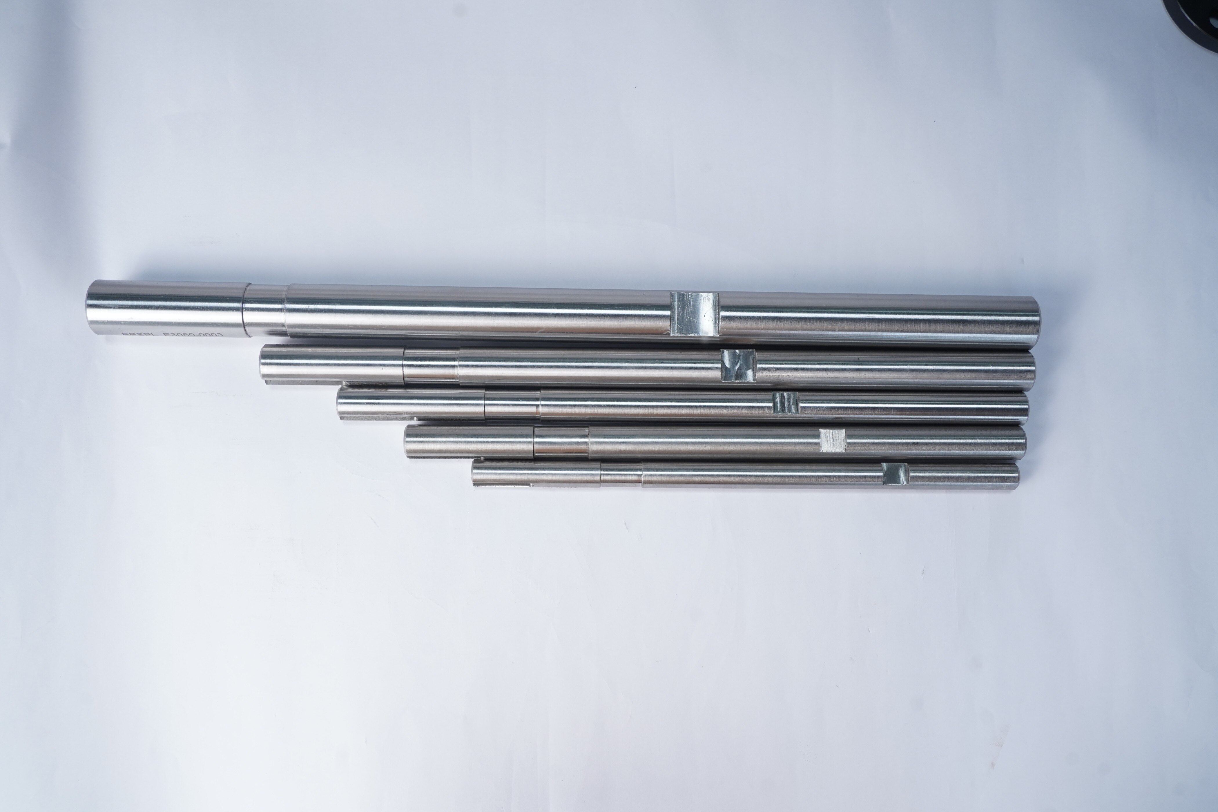
 | Industrial Valve Shaft If you're looking for the highest quality shafts in india and Germany , Efficient Precision is your place. |
Frequently asked questions
What changes when a valve shaft is hollow instead of solid?
A hollow shaft removes material from the centre, reducing weight and rotational inertia while changing torsional strength, bending stiffness and fatigue behaviour.
When is a solid valve shaft the better choice?
Choose a solid shaft when its outside diameter provides enough torque capacity, bending stiffness and fatigue margin without requiring a central bore.
How should you size a hollow valve shaft?
Size the outside diameter, wall thickness and unsupported span together, then check torque, bending, buckling and fatigue at the actual operating loads.
What must you verify before manufacturing a hollow valve shaft?
Verify bore diameter, wall thickness, end closures, seal surfaces, pressure boundaries, tolerances and inspection methods against the valve’s operating requirements.